20.3 ERROR MESSAGE AND SYSTEM ALARM
20.3.2 List of Error Message/System Alarm
20 - 25
17
ADDITION TIMES RESET
FOR MAINTENANCE TIME
NOTIFICATION
18
INSTALLATION OF
COREOS, BOOTOS AND
STANDARD MONITOR OS
19
MAINTENANCE AND
INSPECTION
20
TROUBLESHOOTING
APPENDICESINDEX
406
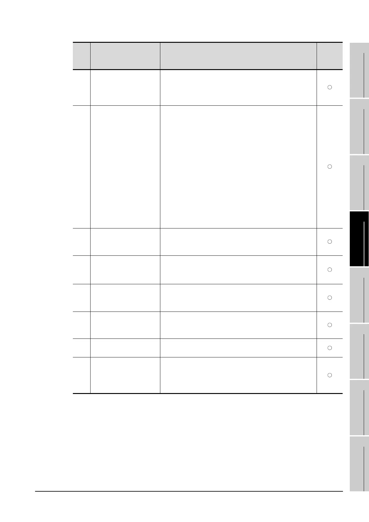
Specified station access is
out of range. Confirm
station no.
1. Station numbers other than master/local station are
specified at the CC-Link connection (via G4).
2. A PLC CPU other than QCPU is accessed.
Confirm the station number of the project data.
407
Accessed other network.
Change network setting.
• When monitoring the same network as the GOT
The GOT accesses the other networks with the MELSEC-
NET/H, MELSECNET/10 (PLC to PLC network), or CC-Link
IE Controller Network connection.Confirm the network
number of the project data so as not to access to other
networks.
• When monitoring other networks
Reconfigure the [Routing Information Setting] of GT
Designer3 or GT Designer2 or the [Routing parameters] of
GX Developer.
• When the GT15-75J71LP23-Z/GT15-75J71BR13-Z is used
These models cannot monitor other networks.
• Confirm Network No. of the project data, in order for not
accessing other networks.
410
Cannot perform operation
because of PLC run
mode. stop the PLC.
The operation, which could not be performed during RUN of
PLC CPU, was performed.
Stop the PLC CPU.
411
Memory cassette is write-
protected. Check the
memory cassette.
The memory cassette installed in the PLC CPU is EPROM or
E
2
PROM, and it is in a protected status.
Confirm the memory cassette installed in PLC CPU.
412
Cannot read/write device
protected by keyword.
Remove keyword.
The key word is set in PLC CPU.
Cancel the key word.
420
E71 specification is
ASCII.
[ASCII code] is selected in [Ethernet operations] of the PLC
side setting.
Select [Binary code].
421
E71 is set as read-only.
Clear setting.
The Ethernet module on the PLC side is set in read-only.
Set the Ethernet module on the PLC side to write-enabled.
422
Not communicating
between CPU and E71.
Confirm CPU error.
PLC CPU error. Communication between PLC CPU and the
PLC side Ethernet module impossible.
Confirm whether there is error in PLC CPU by GX Developer
etc. (Confirm buffer memory)
Error
code
Error message Action
Channel
No.
storage

 Loading...

