20 - 24
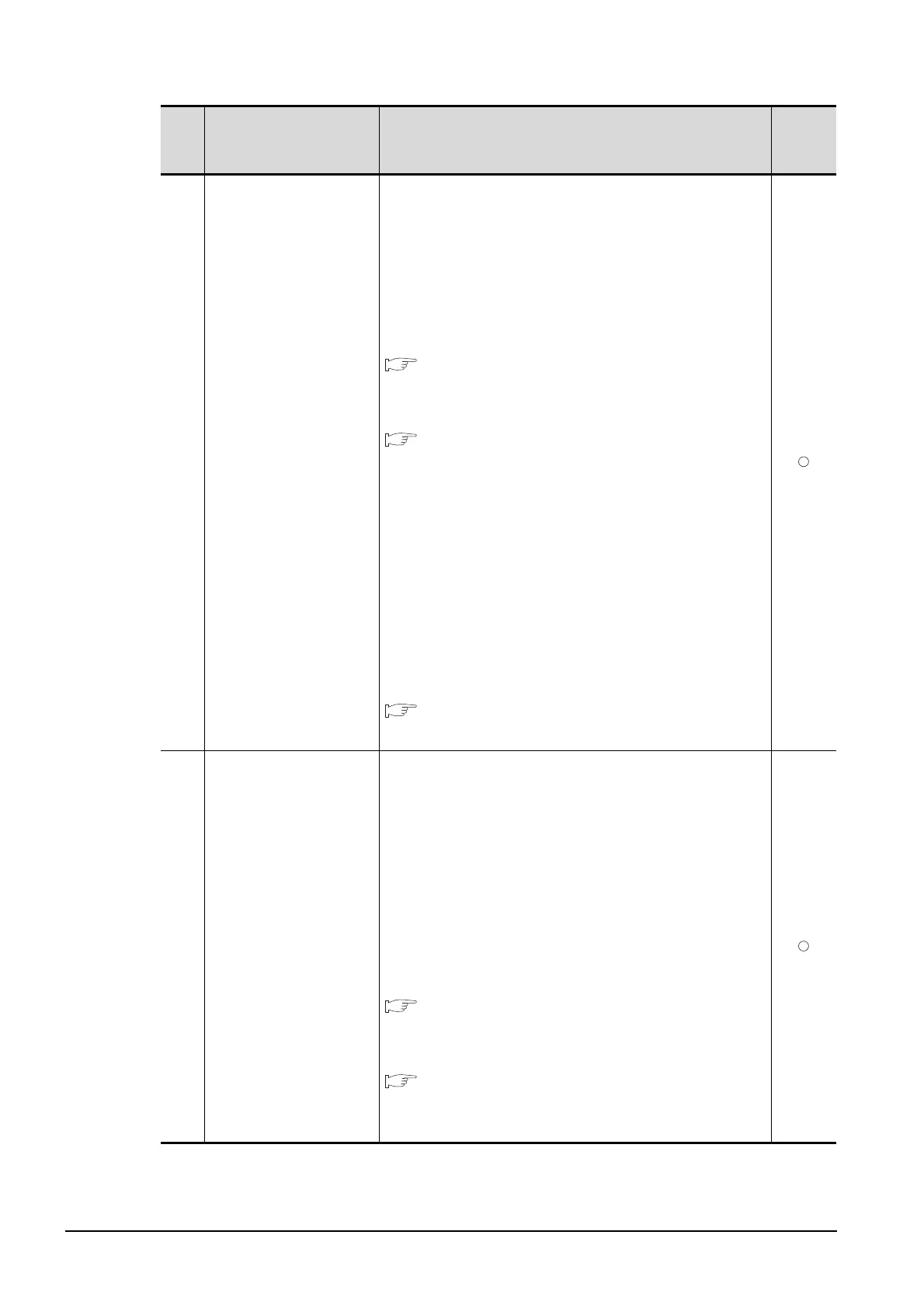
20.3 ERROR MESSAGE AND SYSTEM ALARM
20.3.2 List of Error Message/System Alarm
402
Communication timeout.
Confirm communication
pathway or modules.
The time-out error occurred during communicating.
1. Confirm the cable omission, the communication unit
mounting status and status of the PLC.
Channel No. is not displayed in error code or error
message in the case an error occurs when using the multi-
channel function.
Refer to the following manual to identify the channel No. in
error.
•GOT1000 Series Connection Manual for GT
Works3 and a controller used
(1.6 Checking for Normal Monitoring)
•GOT1000 Series Connection Manual for GT
Designer2/GT Works2 (Description of "Checking
for normal monitoring" of each connection type)
2. may occur when the load of PLC CPU becomes heavier
while accessing other stations. In such case, transfer the
data of the other station to the host station PLC CPU and
monitor them at the host.
3. Put COM instruction when the PLC scanning is long.
4. Check if the version of the communication driver supports
the controller.
For how to check the version of the communication driver,
refer to the following.
•GT Designer3 Version1 Screen Design Manual
(Fundamentals) 8. COMMUNICATION WITH GOT
403
SIO status error. Confirm
communication pathway
or modules.
Either of the overrun error, parity bit error or flaming error was
generated when the RS-422 / RS-232 communication was
received.
Confirm the cable omission, the communication module
mounting status, status of the PLC.and the transmission
speed of the computer link.
Channel No. is not displayed in error code or error message
in the case an error occurs when using the multi-channel
function.
Refer to the following manual to identify the channel No. in
error.
•GOT1000 Series Connection Manual for GT
Works3 and a controller used
(1.6 Checking for Normal Monitoring)
•GOT1000 Series Connection Manual for GT
Designer2/GT Works2 (Description of "Checking
for normal monitoring" of each connection type)
Error
code
Error message Action
Channel
No.
storage

 Loading...