cl
-+
COMPONENT
SERV)CE-IGNIITION SWITCH/METERS AND GAUGES
INSTALLATION
1. Secure the column switch harness and ign$ion switch
harness to the steering column with band chps-to make
sure that the harnesses are not caught in the boss or
moving portion of the column cover.
2. The ignition harness connector and the key-reminder
switch harness connector should be connected to the
front wiring harness together with the column switch
harness connector at the left side of steering support
’ bracket. (16W730)
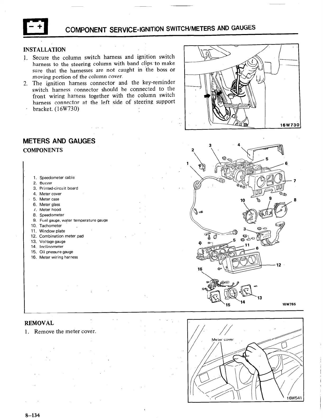
METERS AND GAUGES
COMPONENTS
1. Speedometer cable
2. Buzzer
3. Printed-circuit board
4. Meter cover
5. Meter case
6. Meter glass
7. Meter hood
8. Speedometer
9. Fuel gauge, water temperature gauge
10. Tachometer .
11. Window plate
12. Combination meter pad
13. Voltage gauge
14. Inclinometer
15. Oil pressure gauge
16. Meter wiring harness
16W765
REMOVAL
1. Remove the meter cover.
8-134

 Loading...


