SERVICE ADJUSTMENT PROCEDURES
Charge Rate
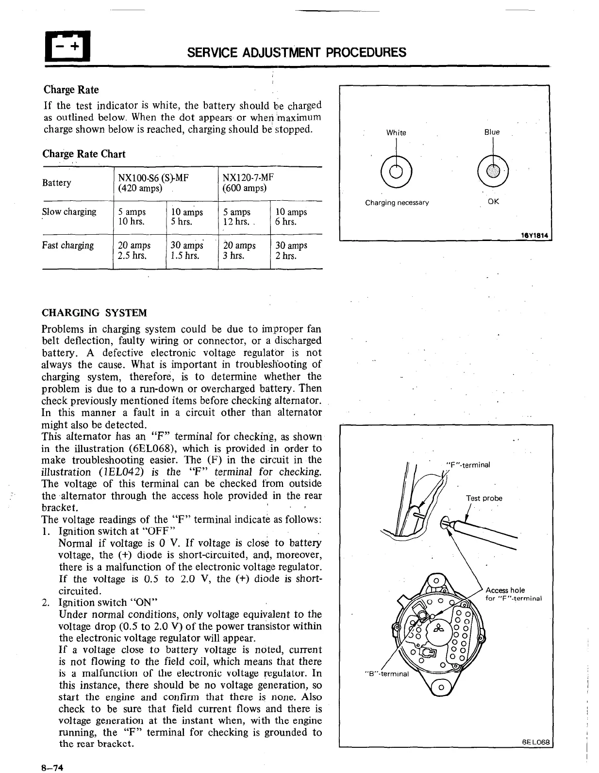
If the test indicator is white, the battery should be charged
as outlined below. When the dot appears or wheri ‘maximum
charge shown below is reached, charging should be’ stopped.
Charge Rate Chart
,I
Battery
Slow charging
Fast charging
NXlOO-S6 (S)MF
(420 amps)
5 amps 10 amps
10 hrs.
5 hrs.
NX120-7-MF
(600 amps)
5 amps 10 amps
12 hrs. 16 hrs.
20 amps 30 amps $0 amps
30 amps
2.5 hrs. 1.5 hrs.
,‘i
3 hrs.
2 hrs.
CHARGING SYSTEM
Problems in charging system could be due to improper fan
belt deflection, faulty wiring or connector, or a discharged
battery. A defective electronic voltage regulatbr is not
always the cause. What is important in troublesli’ooting of
charging system, therefore, is to determine whether the
problem is due to a run-down or overcharged battery. Then
check previously mentioned items before checking alternator.
In this manner a fault in a circuit other than alternator
might also be detected.
This alternator has an “F” terminal for checking,, as shown
in the illustration (6EL068), which is provided in order to
make troubleshooting easier. The (F) in the circuit in the
illustration (lEL042) is the “F” terminal for checking.
The voltage of this terminal can be checked from outside
the -alternator through the access hole provided in the rear
bracket.
’ .,
The voltage readings of the “F” terminal indicatk as follows:
1. Ignition switch at “OFF”
Normal if voltage is 0 V. If voltage is close to battery
voltage, the (+) diode is short-circuited, and, moreover,
there is a malfunction of the electronic voltage regulator.
If the voltage is 0.5 to 2.0 V, the (+) diode is short-
circuited.
2. Ignition switch “ON”
Under normal conditions, only voltage equivalent to the
voltage drop (0.5 to 2.0 V) of the power transistor within
the electronic voltage regulator will appear.
If a voltage close to battery voltage is noted, current
is not flowing to the field coil, which means that there
is a malfunction of the electronic voltage regulator. In
this instance, there should be no voltage generation, so
start the engine and confirm that there is none. Also
check to be sure that field current flows and there is
voltage generation at the instant when, with the engine
running, the “F” terminal for checking is grounded to
the rear bracket.
8-74
Blue
I
Charging necessary
OK
16Vl81
“F’‘-terminal
ccess hole
or “F”-terminal

 Loading...


