COMPONENT SERVICE-CHARGING SYSTEM
REASSEMBLY
Perform reassembly jn reverse procedure of disassembly, pay
attention to the following item:
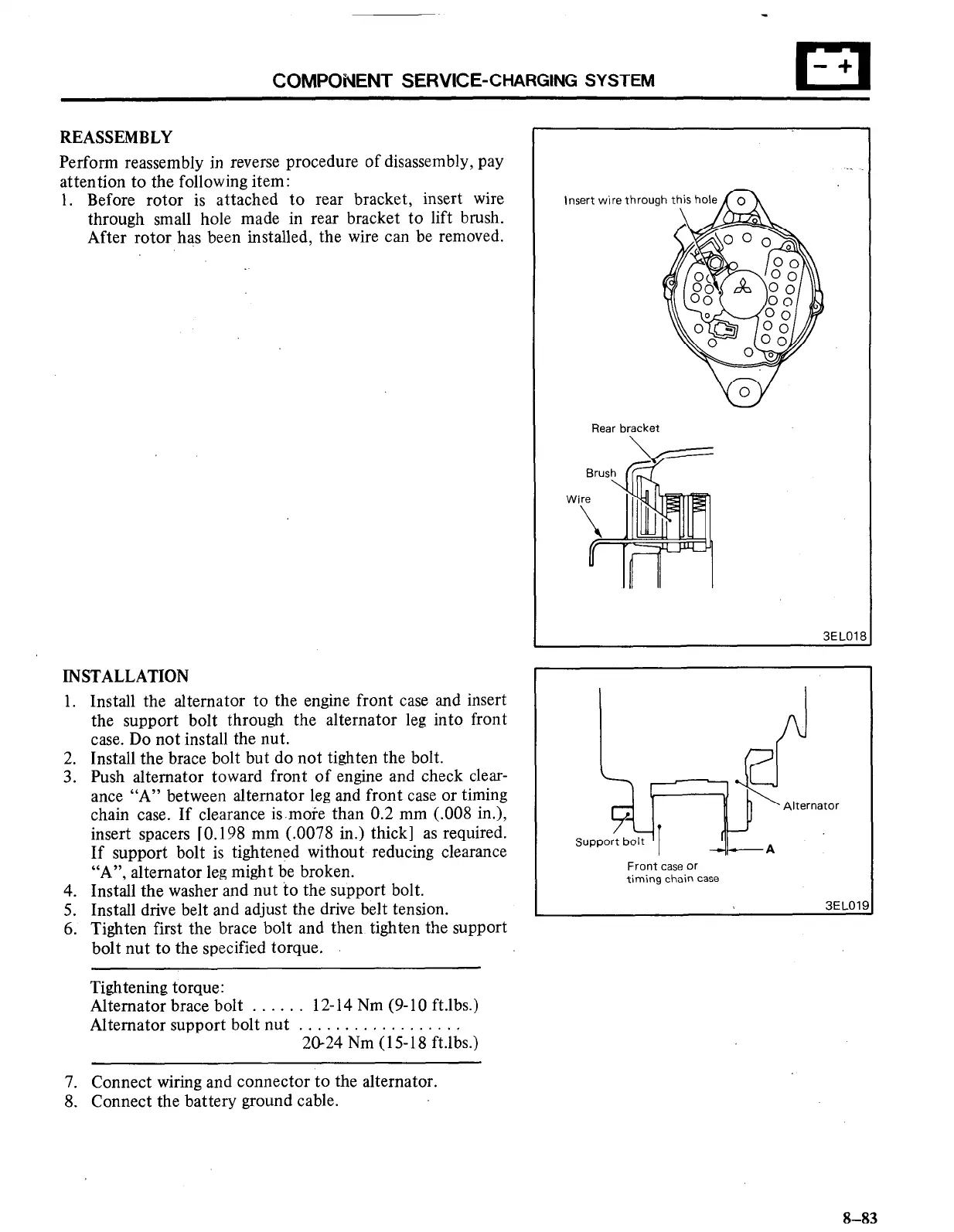
1. Before rotor is attached to rear bracket, insert wire
through small hole made in rear bracket to lift brush.
After rotor has been installed, the wire can be removed.
INSTALLATION
1. Install the alternator to the engine front case and insert
the support bolt through the alternator leg into front
case. Do not install the nut.
2. Install the brace bolt but do not tighten the bolt.
3. Push alternator toward front of engine and check clear-
ance “A” between alternator leg and front case or timing
chain case. If clearance is.more than 0.2 mm (.008 in.),
insert spacers [O. 198 mm (.0078 in.). thick] as required.
If support bolt is tightened without reducing clearance
“A”, alternator leg might be broken.
4. Install the washer and nut to the support bolt.
5. Install drive belt and adjust the drive belt tension.
6. Tighten first the brace bolt and then tighten the support
bolt nut to the specified torque.
Tightening torque:
Alternator brace bolt . . . . . . 12-14 Nm (9-10 ft.lbs.)
Alternator support bolt nut . . . . . . . . . . . . . . . . . ,
20-24 Nm (15-l 8 ft.lbs.)
I nsel ‘t wire throw
Rear bracket
3EI nlF
2:
Alternator
Support bolt
I
-A
Front case or
timing chain case
3ELOlE
7. Connect wiring and connector to the alternator.
8. Connect the battery ground cable.
8-83

 Loading...


