COMPONENT SEIRVICE-CHARGING
SYSTEM
DISASSEMBLY
1. Remove the three through bolts.
2. Insert
plain
screwdriver between front bracket and-stator
core and
pry
downward. (3EL029)
Caution
Do not insert screwdriver too deep, as there is danger of
damage to stator coil.
3. Clamp the rotor in a vise with pulley side up (protect
rotor from vise jaws).
4. Remove pulley nut. Then remove spring washer, pulley,
fan and collar.
5. ,Remove front bracket and two seals.
6. Remove the rotor from vise.
7. Remove the nut from “B” terminal and remove the
washer and condenser.
8. Remove the brush holder screw and rectifier screws.
9. Remove the stator assembly from the rear bracket.
10. When stator is to be removed, unsolder three stator
leads soldered to main diodes on rectifier. (3EL046)
Caution
1. When soldering or unsoldering, use care to make sure
that heat of soldering iron is not transmitted to diodes
for a long period. Finish soldering or unsoldering in as
short a time as possible.
2. Use care that no undue force is exerted to leads of diodes.
11. When separate the rectifier from brush holder, unsolder.
two plates soldered to rectifier.
INSPECTION
Rotor
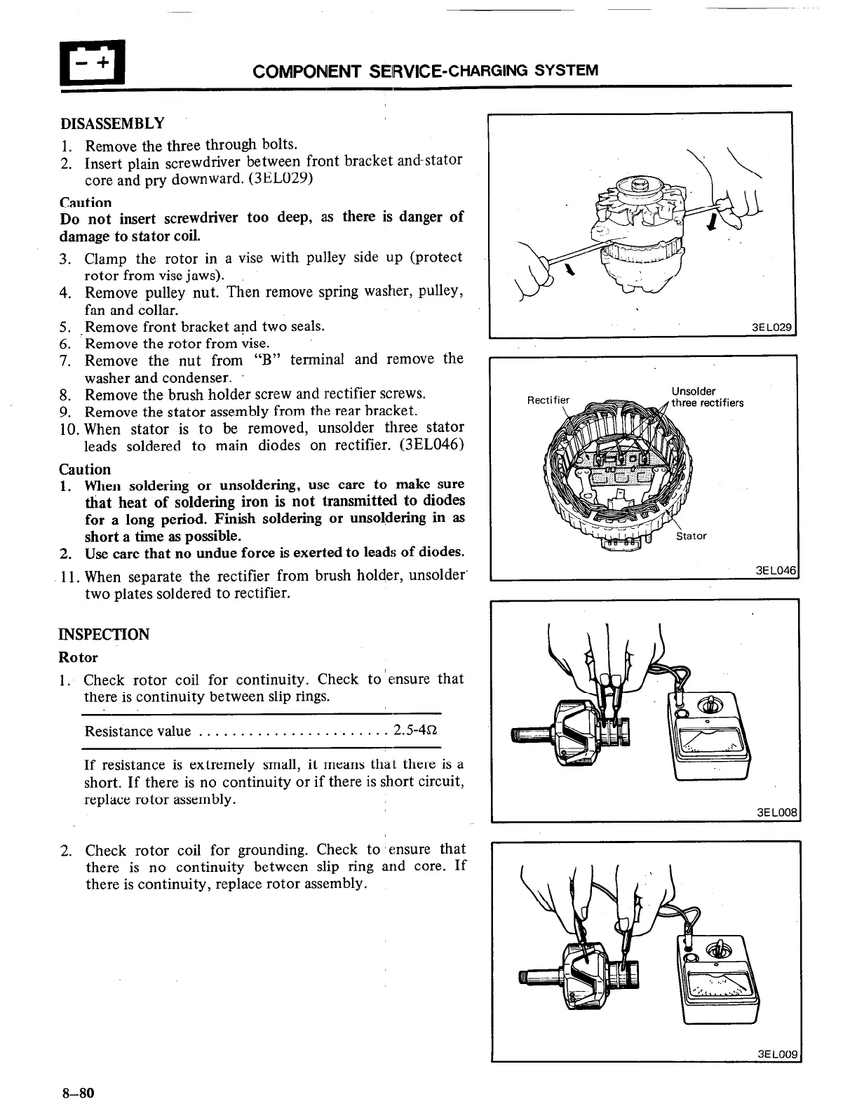
1, Check rotor coil for continuity. Check to ‘ensure that
there is continuity between slip rings.
Resistance value . . . . . . . . . . . . . . . . . . . . . . . 2.5-4s
If resistance is extremely small, it means that there is a
short. If there is no continuity or if there is short circuit,
replace rotor assembly.
2. Check rotor coil for grounding. Check to ‘ensure that
there is no continuity between slip ring and core. If
there is continuity, replace rotor assembly.
I
3E LO2!
Unsolder
hree rectifiers
3
'I
3
I
3EL04f
3E LOO1
3
8-80

 Loading...


