SERVICE ADJUSTMENT PROCEDURES/
COMPONENT SERVICE-CHARGING
SYSTEM
n
-+
1.
2.
3.
4.
Remove the distributor cap.
Check signal rotor position in relation to the pick-up. If
it is not the position shown in the illustration (6EL069),
turn the crankshaft manually so that the projection of
the signal rotor is moved away from the center part of
the pick-up. In other words, the signal rotor should be
positioned so that current can flow to the ignition coil.
Disconnect the high-tension cable from the center tower
of the distributor cap, and hold the end of the cable
about 5 to 10 mm (.2 to .4 in.) away from the cylinder
block of the engine. (lEL038)
Turn the ignition switch to “ON”. Then, when a piece of
metal (the tip of a screwdriver for instance) is inserted
into the detection coil of the pick-up and then moved
away, a spark can be generated. (6EL069)
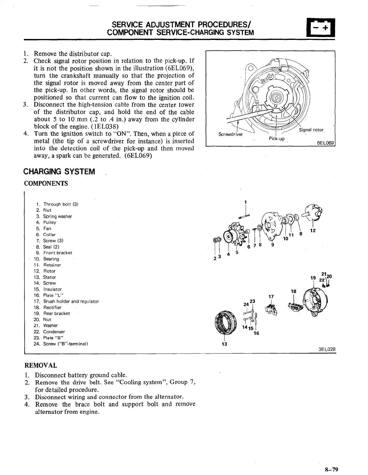
CHARGING SYSTEM
COMPONENTS
1. Through bolt (3)
2. Nut
3. Spring washer
4. Pulley
5. Fan
6. Collar
7. Screw (3)
8. Seal (2)
9. Front bracket
10. Bearing
11. Retainer
12. Rotor
13. Stator
14. Screw
15. Insulator
16. Plate “L”
17. Brush holder and regulator
18. Rectifier
19. Rear bracket
20. Nut
21. Washer
22. Condenser
23. Plate “6”
24. Screw (“B’‘-terminal)
Pick-up
REMOVAL
1. Disconnect battery ground cable.
2. Remove the drive belt. See “Cooling system”, Group 7,
for detailed procedure.
3. Disconnect wiring and connector from the alternator.
4. Remove the brace bolt and support bolt and remove
alternator from engine.
8-79

 Loading...


