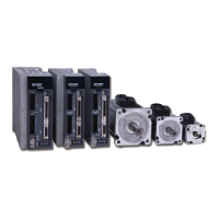
M Series AC Servo
User Manual
5
Rev. 1.0
7/31/2019
400-820-9661
7.1.4 Global Gain Switch Function ..................................................................................78
7.1.5 Control Mode Switch ..............................................................................................79
7.1.6 Drive On Fault Output ............................................................................................80
7.1.7 Motor Brake Control ..............................................................................................81
7.1.8 Servo Ready Output .............................................................................................. 82
7.2 Position Mode .................................................................................................................82
7.2.1 Digital Pulse Position Mode Connection Diagram .................................................. 83
7.2.2 Input Pulse Type And Input Noise Filter ................................................................83
7.2.2.1 Input Pulse Type Setting ............................................................................84
7.2.2.2 Input Noise Filter Setting ............................................................................84
7.2.2.3 Parameter P-43 (SZ) Setting .....................................................................85
7.2.3 Control Pulse Dividing Switch Function ..................................................................86
7.2.4 Pulse Inhibition Function .......................................................................................87
7.2.5 Electronic Gearing Ratio ........................................................................................87
7.2.6 Jerk Smoothing Filter .............................................................................................88
7.2.7 In Position Error Output .......................................................................................... 89
7.2.8 Gain Parameters For Position Control Mode .........................................................89
7.2.9 Software Conguration For Position Mode .............................................................90
7.3 Velocity Mode .................................................................................................................91
7.3.1 Velocity Mode Connection Diagram .......................................................................92
7.3.2 Parameter Settings For Analog Velocity Control Mode ..........................................93
7.3.3 Basic Settings For Analog Velocity Control Mode ..................................................93
7.3.3.1 Command Signal For Analog Velocity Mode ..............................................93
7.3.3.2 Analog Velocity Gain ..................................................................................94
7.3.3.3 Analog Input Voltage Offset .......................................................................95
7.3.3.4 Analog Input Deadband .............................................................................96
7.3.3.5 Run/Stop And Direction Signal ..................................................................97
7.3.3.6 Torque Limit ..............................................................................................98
7.3.3.7 Target Velocity Reach ................................................................................99
7.3.4 Analog Input Filter ................................................................................................100
7.3.5 Software Conguration For Analog Velocity Mode ...............................................101
7.4 Torque Mode .................................................................................................................102
7.4.1 Analog Torque Mode Connection Diagram ...........................................................103
7.4.2 Parameters For Analog Torque Mode ..................................................................104
7.4.3 Basic Settings For Analog Torque Mode ..............................................................104
7.4.3.1 Command Signal For Analog Torque Mode ............................................104
7.4.3.2 Analog Torque Gain .................................................................................105
7.4.3.3 Analog Input Offset ..................................................................................106
7.4.3.4 Analog Deadband ....................................................................................106
7.4.3.5 Run/Stop and Direction signal ................................................................107
7.4.3.6 Velocity Limit ...........................................................................................107
7.4.3.7 Torque Reach ..........................................................................................108
7.4.4 Software Conguration For Analog Torque Mode ................................................109

 Loading...