7 Functions and settings
© Maschinenfabrik Reinhausen 2012 2117246/02 EN TAPCON® 230 basic 117
To set the current transformer connection, proceed as follows:
1. > Configuration > Transformer
data > 3x
.
<03> Current Transformer Connection.
2. Press
or to to select a current trans-
former connection
3. Press
.
The current transformer connection is set.
7.4.1.5 Setting the phase difference for the current/voltage transformer
The normal measuring circuit values can be set as follows:
System Setting Display
1 phase 0 0 1PH
3 phase 0 0 3PH
3 phase 90 90 3PH
3 phase 30 30 3PH
3 phase -30 -30 3PH
Table 35 Setting options for the measuring circuits
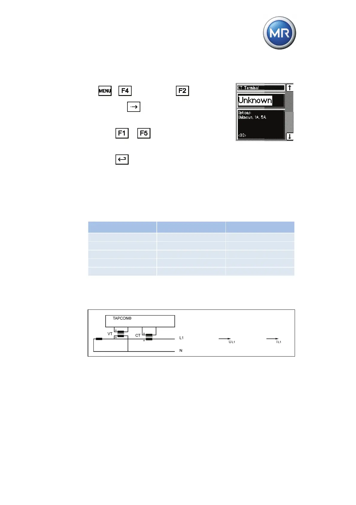
Circuit a (1 phase):
Figure 32 Circuit a - phase difference "0 1PH"
The voltage transformer VT is connected to the outer conductor and neu-
tral.
The current transformer CT is looped into the outer conductor.
The voltage V
L1
and current I
L1
are in phase.
The voltage drop on an outer conductor is determined by the current I
L1
.