7 Functions and settings
© Maschinenfabrik Reinhausen 2012 2117246/02 EN TAPCON® 230 basic 119
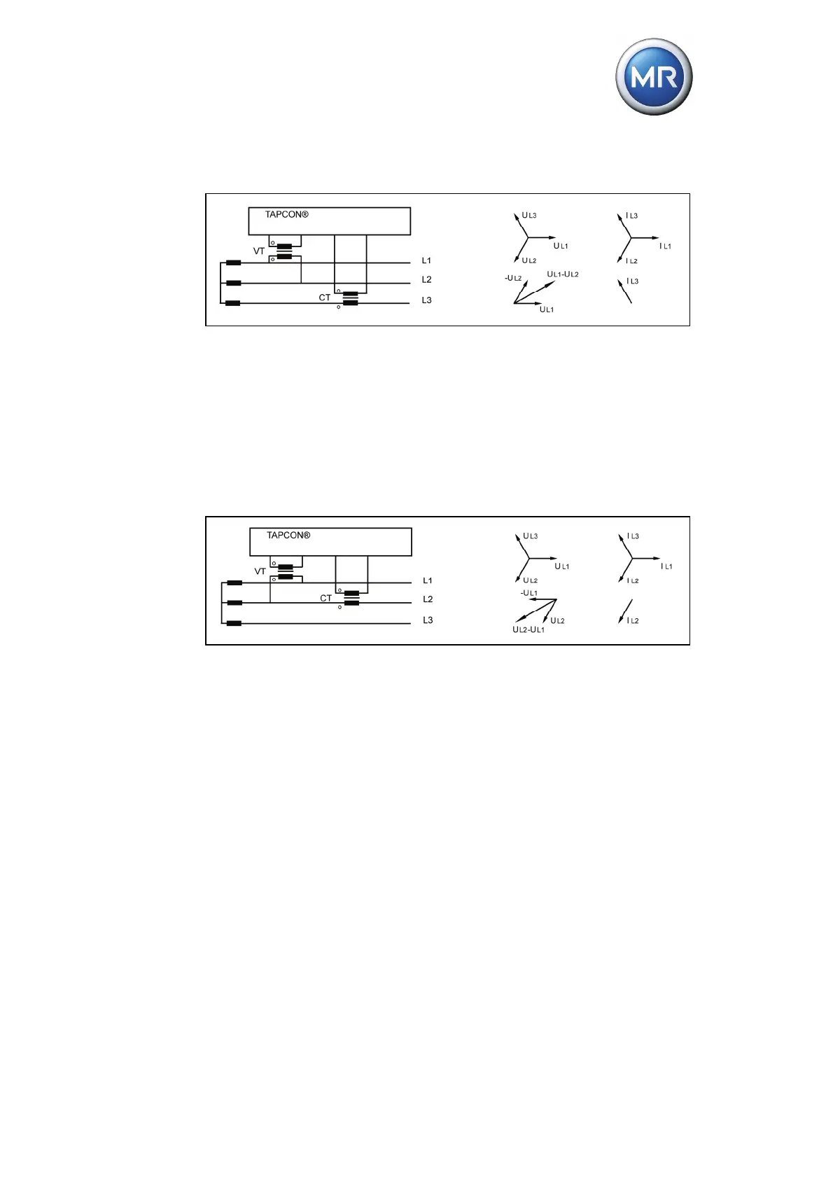
Circuit c:
Figure 35 Circuit c - phase difference "90 3PH"
The voltage transformer VT is connected to the outer conductors L1 and
L2.
The current transformer CT is looped into the outer conductor L3.
The current I
L3
is ahead of voltage V
L1 L2
by 90°.
The voltage drop on an outer conductor is determined by the current I
L3
.
Circuit d:
Figure 36 Circuit d - phase difference "30 3PH"
The voltage transformer VT is connected to the outer conductors L1 and
L2.
The current transformer CT is looped into the outer conductor L2.
The current I
L2
is ahead of voltage V
L1 L2
by 30°.
The voltage drop on an outer conductor is determined by the current I
L2
.