7 Functions and settings
120 TAPCON® 230 basic 2117246/02 EN © Maschinenfabrik Reinhausen 2012
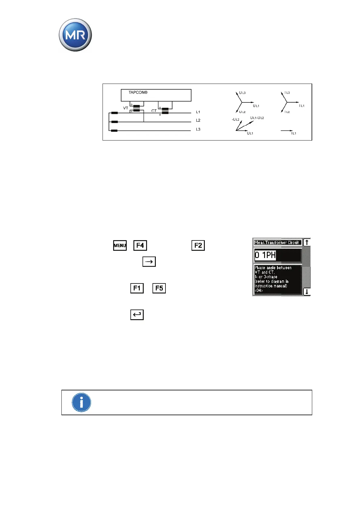
Circuit e:
Figure 37 Circuit e - phase difference "-30 3PH"
The voltage transformer VT is connected to the outer conductors L1 and
L2.
The current transformer CT is looped into the outer conductor L1.
The current I
L1
lags behind voltage V
L1 L2
by 30°. This corresponds to a
phase shift of -30°.
The voltage drop on an outer conductor is determined by the current I
L1
.
To set the phase difference for the measured transformer circuit, proceed as
follows:
1. > Configuration > Transformer
data > 4x
.
<04> Transformer Circuit.
2. Press
or to to select a setting for
the phase difference.
3. Press
.
The phase difference is set.
7.4.1.6 Setting the voltage display kV/V
Switching the display from V to kV converts the measurements and setting
values in the device on the primary side of the voltage transformer and dis-
plays them accordingly. However, the primary side is always displayed in kV
and the secondary side always in V.
The display can only be changed from V to kV if all the transformer data have
previously been entered.