7 Functions and settings
© Maschinenfabrik Reinhausen 2012 2117246/02 EN TAPCON® 230 basic 133
7.4.2.10 Wiring and parameterizing control input/output relay
If you want to monitor the motor runtime, the voltage regulator and motor-
drive unit must be connected and parameterized as shown below.
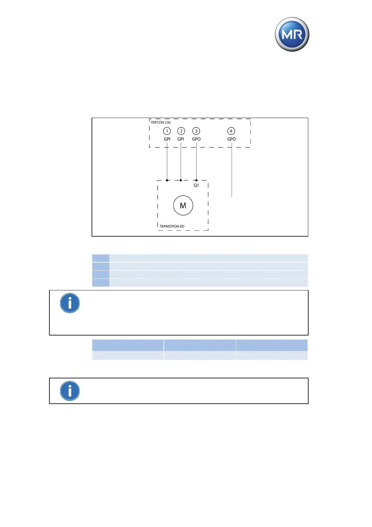
Figure 40 Wiring for motor runtime monitoring
1 GPI "Motor running"
2 GPI "Motor protective switch tripped" (optional)
3 GPO "Motor protective switch tripped" (optional)
4 GPO "Motor runtime exceeded" (optional)
In order to be able to use the GPOs, you must wire the feedback from the
motor-drive unit "Motor protective switch tripped" to a GPI and parameterize
the GPI (see "Assigning function to inputs (GPIs)" on page 135). This
message resets the "Motor runtime exceeded" GPO when the motor protec-
tive switch is switched back on and activates the "Motor protective switch
tripped" message.
Setting range Step size Factory setting
0 s...30 s 0.1 s 0 s
Table 39 Setting range for motor runtime
To deactivate motor runtime monitoring, set the motor runtime to "0.0 s".