5 Mounting
58 TAPCON® 230 basic 2117246/02 EN © Maschinenfabrik Reinhausen 2012
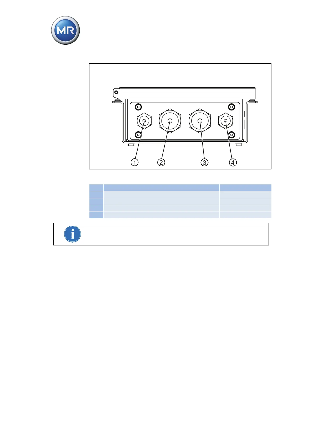
Figure 26 Recommendation for cable bushing
No. Cable Terminal
1 Power supply X2: 3/4
2 Voltage measurement, current measurement X2:1/2, X1:5/6/9
3 Relay outputs X3:1-12, X4:1-12
4 Signal inputs X4:13-24
Any M screw connections not needed must be sealed with dummy plugs to
ensure an IP54 degree of protection.
5. Strip insulation from lines and leads.
6. Compress stranded wires with core cable ends.
7. Guide lines through M screw connection.
8. Guide leads into corresponding connector terminals and secure by tighten-
ing screws.
9. Guide M screw connection plate onto the device opening provided for this
purpose.
10. Plug connectors into the correct slots.
11. Secure M screw connection plate to device housing with 4 hexagon socket
screws.
12. Tighten M screw connections. The M screw connections provide traction
relief.