6 Functions and settings
Maschinenfabrik Reinhausen 201476 2374092/04 ENTAPCON® 260
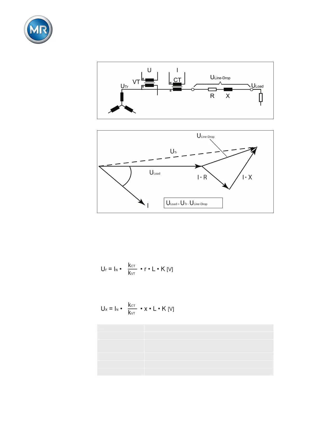
Figure 47: Equivalent circuit
Figure 48: Phasor diagram
You can calculate the ohmic and inductive voltage drop using the following
formulas. This voltage drop calculation relates to the relativized voltage on
the secondary side of the voltage transformer.
Formula for calculating the ohmic voltage drop:
Formula for calculating the inductive voltage drop:
U
r
Ohmic resistance load in Ω/km
U
x
Inductive resistance load in Ω/km
I
N
Nominal current (amps) of selected current-trans-
former connection on device:0.2 A; 1 A; 5 A
k
CT
Current transformer ratio
k
VT
Voltage transformer ratio
r Ohmic resistance load in Ω/km per phase