6 Functions and settings
Maschinenfabrik Reinhausen 201488 2374092/04 ENTAPCON® 260
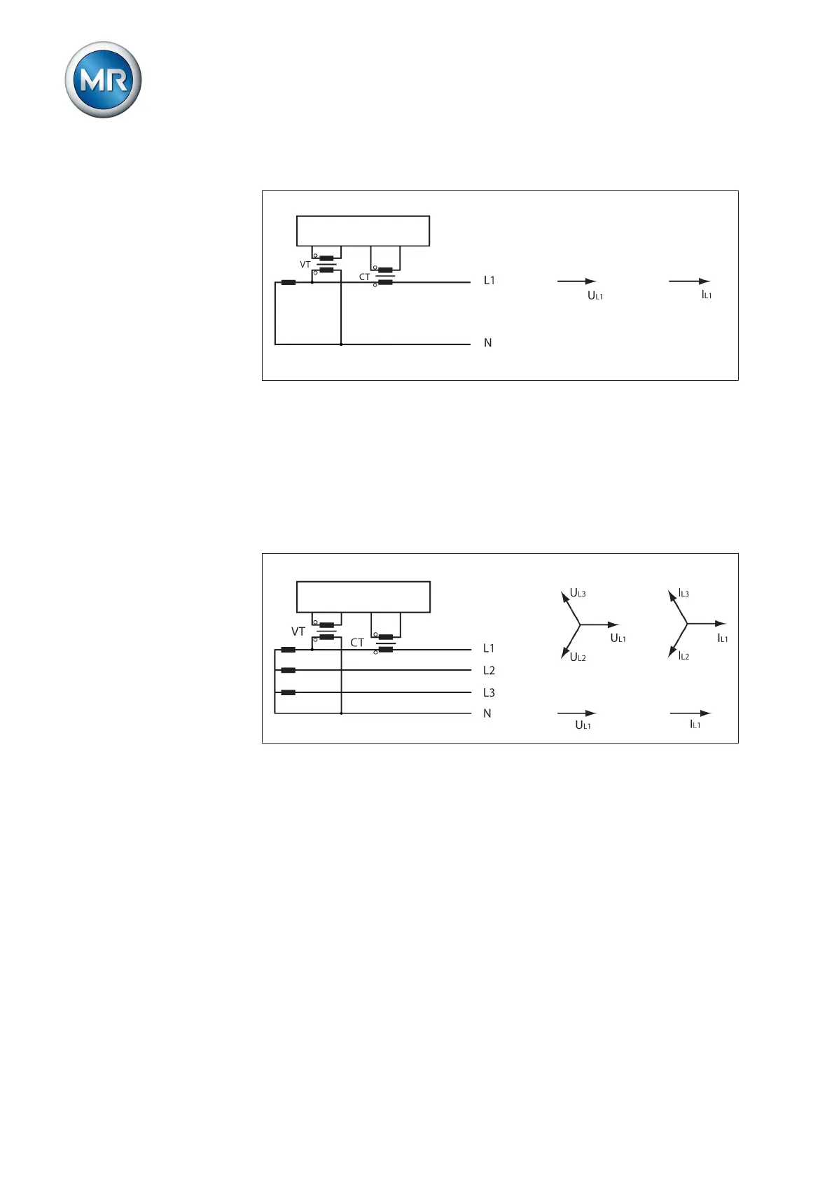
Circuit A: 1-phase measurement in 1-phase grid
Figure 51: Phase difference 0 1PH
▪ The voltage transformer VT is connected to the outer conductor and
neutral conductor.
▪ The current transformer CT is looped into the outer conductor.
▪ The voltage U
L1
and current I
L1
are in phase.
▪ The voltage drop on an outer conductor is determined by the current I
L1
.
Circuit B: 1-phase measurement in 3-phase grid
Figure 52: Phase difference 0 3PHN
▪ The voltage transformer VT is connected to the outer conductors L1 and
neutral.
▪ The current transformer CT is looped into the outer conductor L1.
▪ The voltage U and current I are in phase.
▪ The voltage drop on an outer conductor is determined by the current I
L1
.