6 Functions and settings
Maschinenfabrik Reinhausen 2014 892374092/04 EN TAPCON® 260
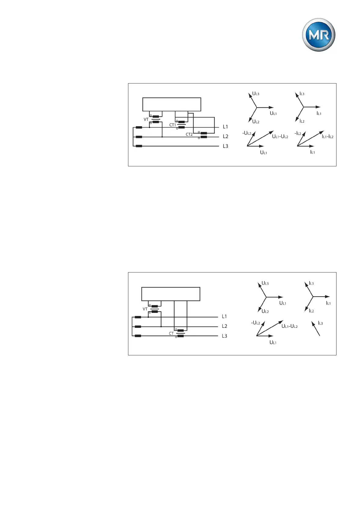
Circuit C:
Figure 53: Phase difference 0 3PH
▪ The voltage transformer VT is connected to the outer conductors L1 and
L2.
▪ The current transformer CT1 is looped into the outer conductor L1 and
CT2 into the outer conductor L2.
▪ The current transformers CT1 and CT2 are connected crosswise in par-
allel (total current = I
L1
+ I
L2
).
▪ The total current I
L1
+ I
L2
and voltage U
L1
-U
L2
are in phase.
▪ The voltage drop on an outer conductor is determined by the current:
(I
L1
+ I
L2
) / √3.
Circuit D
Figure 54: Phase difference 90 3PH
▪ The voltage transformer VT is connected to the outer conductors L1 and
L2.
▪ The current transformer CT is looped into the outer conductor L3.
▪ The current I
L3
is ahead of voltage U
L1
-V
L2
by 90°.
▪ The voltage drop on an outer conductor is determined by the current I
L3
.