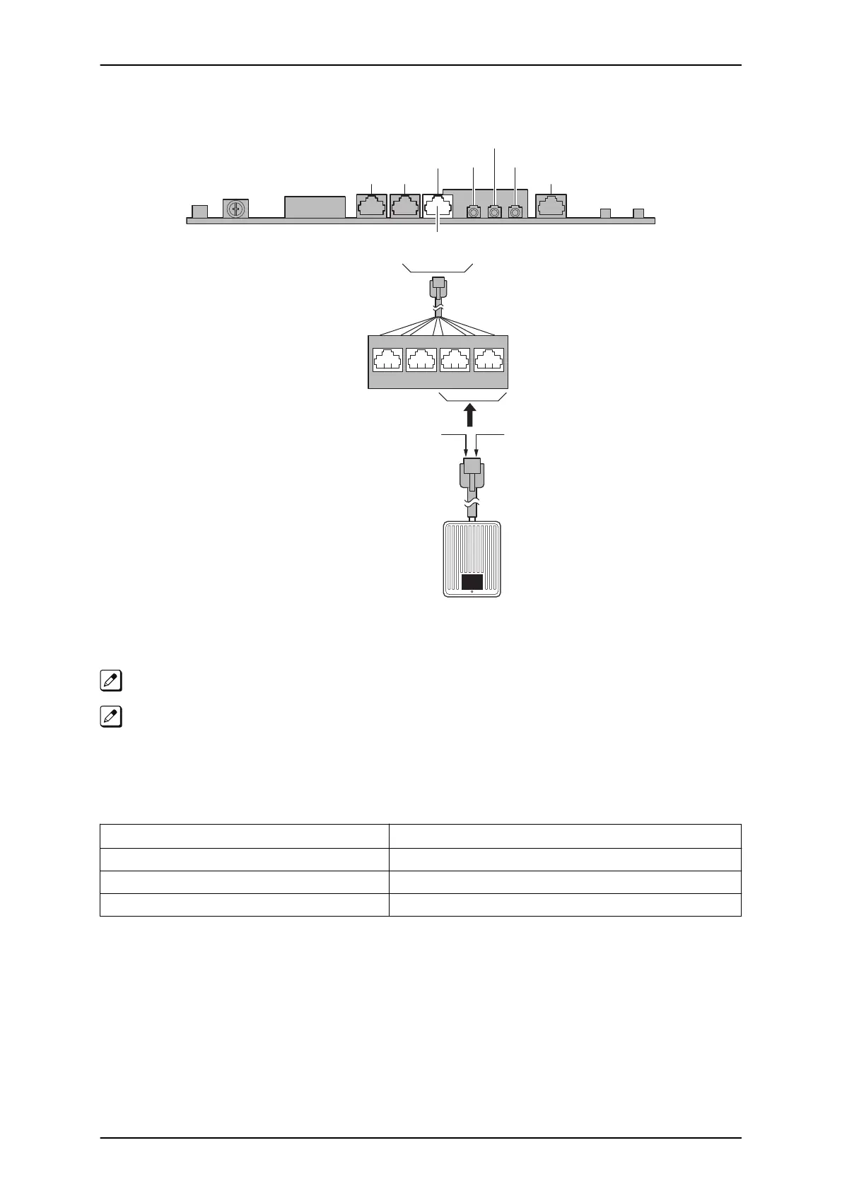
5.5.2 Connecting the Doorphone
TR
Doorphone
Modular Cable
(2-wire, Straight)
T : Tip
R : Ring
J102
5
Port 1 Port 2 Port 3 Port 4
43 6 2 71 8
J101 J7
RY1/2
J103 J431 J411
J421
SLI 9-12
/DPH 1-2
Figure 2-119 Connecting the Doorphone
The Doorphone configuration is assigned using system programming.
The 3
rd
party Doorphone Boxes cannot be connected to the port.
5.5.3 Doorphone Interface Specifications
Table 2-23 Doorphone Interface Specifications
Item Specification
Output Impedance 600 Ω
Output Level Nominal 250 mV (-10 dBm)
Maximum Output 400 mV RMS
5.6 Installing the Door Unlock Devices
A maximum of two door unlock devices can be connected to the KSU.
ISSUE 4.1 (R5.1)
SL1100
Hardware Manual 2-79
 Loading...


