For the details of PZ-VM21 daughter board installation, refer to Installing the PZ-VM21 PCB on
page 2-62.
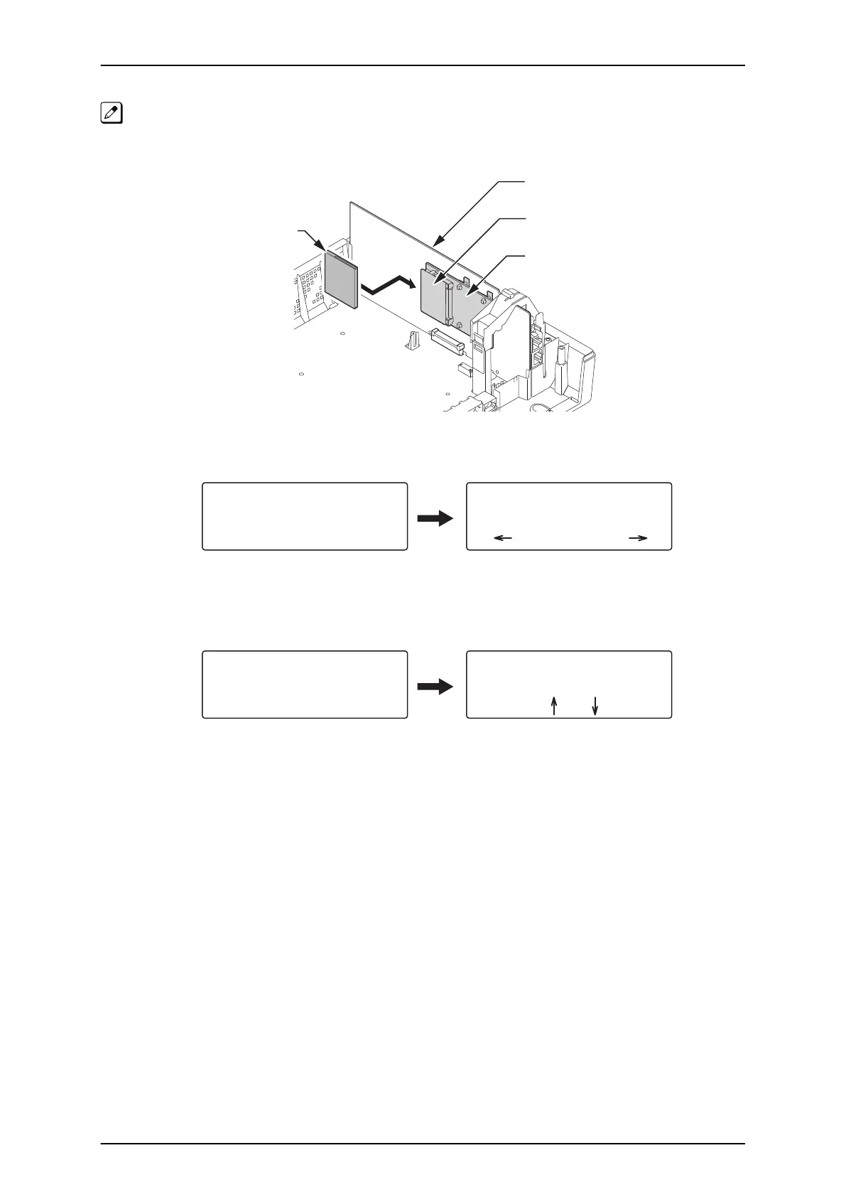
1. Turn the power off, insert the Customer Data CF card into the CF Slot on PZ-VM21.
CPU card
CF Slot (CN2)
CF card
PZ-VM21 PCB
Figure 3-13 Inserting the CF card
2. Turn the power on, enter the Program Mode then PRG90-04.
Program Mode
Base Service OP1 OP2
90-04-01
Data Load YES:1 1
Figure 3-14 PRG90-04 Display
3. Dial 1 and press Hold key.
4. When the data backup to the CF card is completed, the display changes to the next PRG.
Loading System Data
90-05- M
’
tenance
Slot Control |01
back Select
Figure 3-15 Next PRG Display
5. Remove the CF card and exit from the Program Mode.
SL1100 ISSUE 4.1 (R5.1)
3-6 System Start Up
 Loading...


