3.3.3 Mounting the 2BRIDB PCB
Set the switches on the 2BRIDB-C1 PCB before mounting onto the 084M-
B1/080E-B1/008E-B1/000E-B1 PCB, refer to the Switch Setting on
page 2-49.
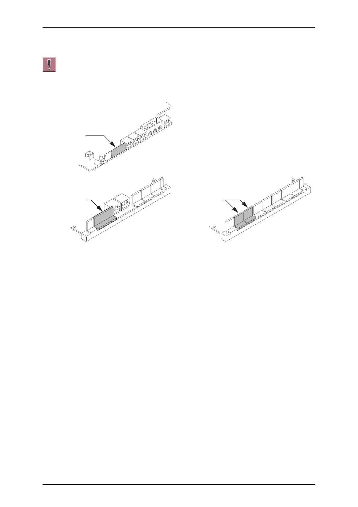
1. Cut and remove specified Plastic Knockouts on the 084M-B1/080E-B1/008E-B1/000E-B1 PCB.
084M-B1
080E-B1/008E-B1
Plastic
Knockout
Plastic
Knockout
000E-B1
Plastic
Knockouts
Figure 2-64 Plastic Knockouts on 084M-B1/080E-B1/008E-B1/000E-B1
2. Insert two Nylon-spacers into the specified holes. Using supplied screw, fasten Metal Spacer to
2BRIDB-C1 PCB.
3. Mount the 2BRIDB-C1 PCB onto the 084M-B1/080E-B1/008E-B1/000E-B1 PCB using two Nylon-
spacers and one screw. (Refer to Figure 2-65 Installing the 2BRIDB-C1 on page 2-43)
SL1100 ISSUE 4.1 (R5.1)
2-42 Installation