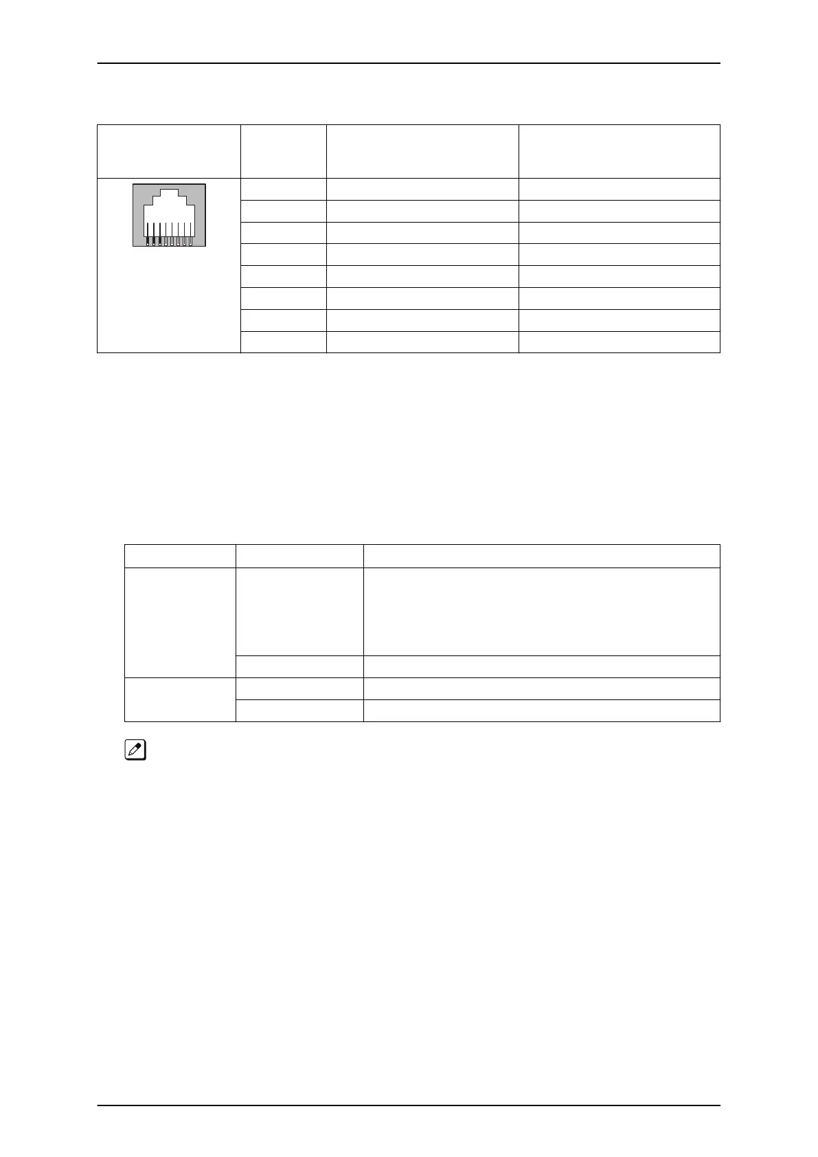
Table 2-12 RJ-61 BRI Pin-Outs (S-Bus, T-Bus)
Pin No. RJ-61 Cable Connec-
tor-2BRIDB-J2 (BRI1), J3
(BRI2) S-Bus Connection
RJ-61 Cable Connector-2BRIDB-
J2 (BRI1), J3 (BRI2) T-Bus Con-
nection
1 - -
2 - -
3 RA TA
4 TA RA
5 TB RB
6 RB TB
7 - -
8 - -
3.4.5.2 Switch Setting
Figure 2-72 Switches Location of 2BRIDB-C1 on page 2-50 shows the location of the connectors and
switches on the IP4WW-2BRIDB-C1.
1. Set the switches J12 to J17 according to the system, referring the Table 2-13 Switch Setting of
2BRIDB-C1 on page 2-49.
Table 2-13 Switch Setting of 2BRIDB-C1
Switch No. Switch Position Description
J12/J15 ON (default) Termination register is ON.
This SW should be ON in case:
• T-Bus Point-to-Point connection is selected.
• T-Bus Point-to-Multipoint is selected, and if the system is Terminal 8.
(last device on the bus)
• S-Bus.
OFF P-MP (Terminal 7)
J13, J14/J16, J17 T (default) T-Bus connection
S S-Bus connection
J12 & J15 do not configure the connection type on the system, they only add/remove the termination
of the circuit.
J13,J14 & J16, J17 do not configure the connection type on the system, they only select the polarity of
the connector J2/J3.
The 2BRIDB-C1 circuits must also be setup within the system configuration.
ISSUE 4.1 (R5.1) SL1100
Hardware Manual 2-49