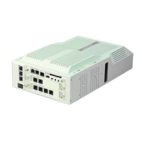
2. Connect the cables from the NT1 Network Termination cable to the J2 or J3 connector on the
2BRIDB-C1 daughter board.
Connector J2 - BRI1: Use switches J12, J13, J14
Connector J3 - BRI2: Use switches J15, J16, J17
Ensure that you set all switches correctly for each BRI circuit.
J3J2
BRI 2BRI 1
J12
J13 J14
J15
J16 J17
J12/15
ON OFF
J13/16
TS
J14/17
TS
IP4WW-2BRIDB-C1
Figure 2-72 Switches Location of 2BRIDB-C1
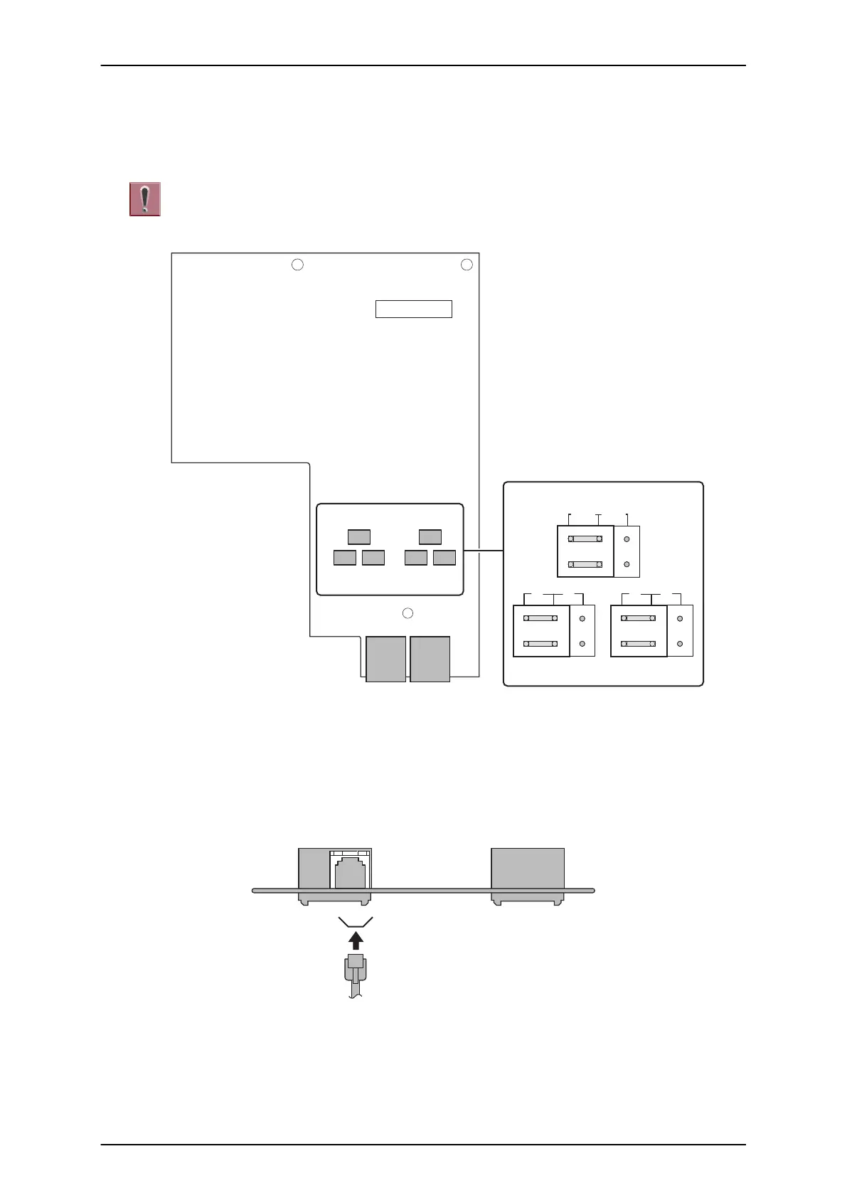
3.4.6 Cabling and Setting IP4WW-1PRIU-C1
This IP4WW-1PRIU-C1 PCB provides one RJ-45 PRI connection.
Figure 2-73 Connector of 1PRIU-C1
SL1100
ISSUE 4.1 (R5.1)
2-50 Installation