Chapter 2 - Blade Installation and Startup
Chapter 2 2 - 39
SECTION 2-5
Station Blades
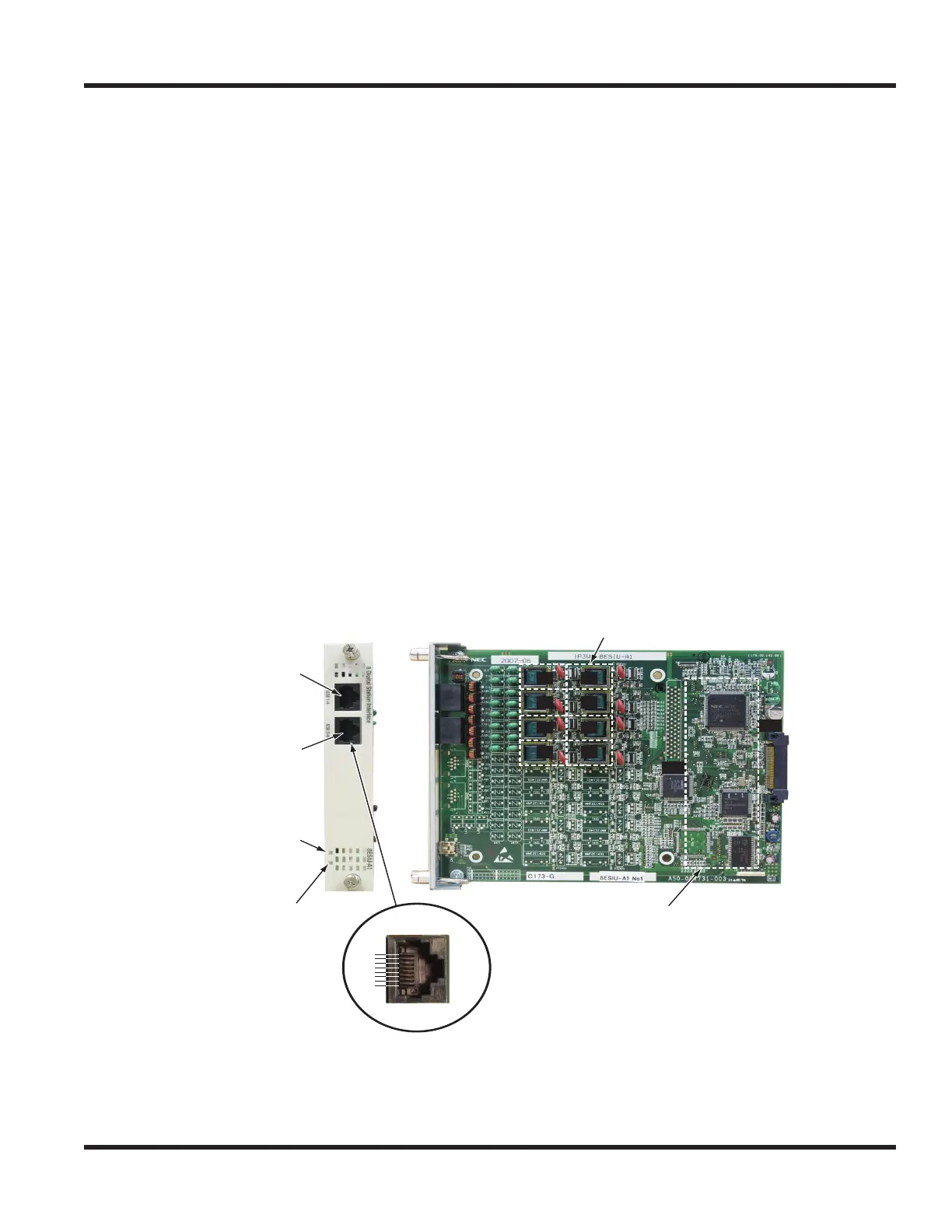
2.5.1 Digital Station (8/16ESIU) Blade (Figure 2-19) - P/N 0911036 and 0911038
The ESIU blade provides:
● 8 (8ESIU) OR 16 (16ESIU) digital extension circuits (used for digital terminals, DSS consoles, SLTAD
adapters, 2PGDAD adapters)
● These ports provide -48V feeding.
● 2 Blade status LEDs - 1 Live LED, 1 Busy/Idle LED
● Compatible with most Aspire keysets (all digital and IP terminals, CTA and CTU adaptors - not, however,
Aspire Soft Phone, Aspire Wireless, etc.)
The ESIU can be installed in any universal slot in the system and up to a maximum of 20 ESIU blades installed
per 4-chassis system, providing up to 320 digital ports. A maximum of 16 2B channels per chassis is possible.
With CygniLink and a 7-chassis system, the maximum number of blades is 32.
Per 19” chassis, there is a maximum of 80 digital or analog station ports allowed.
Figure 2-19: 8ESIU BLADE
CN101
Key Telephone
Interface
#1- #4
CN201
Key Telephone
Interface
#5- #8
BUSY LED
(Status for terminals)
ON: Extension(s)
in Use
OFF: Idle
LIVE LED
(Status LED)
Interface Circuit #
Common
Control
Circuit
CN
101
CN
201
CN2
CN1
#2 #1
#3 #4
#6 #5
#7 #8
1
2
3
4
5
6
7
8
Pin Number
Location
RJ61
Connector

 Loading...


