2 - 88 Chapter 2
Chapter 2 - Blade Installation and Startup
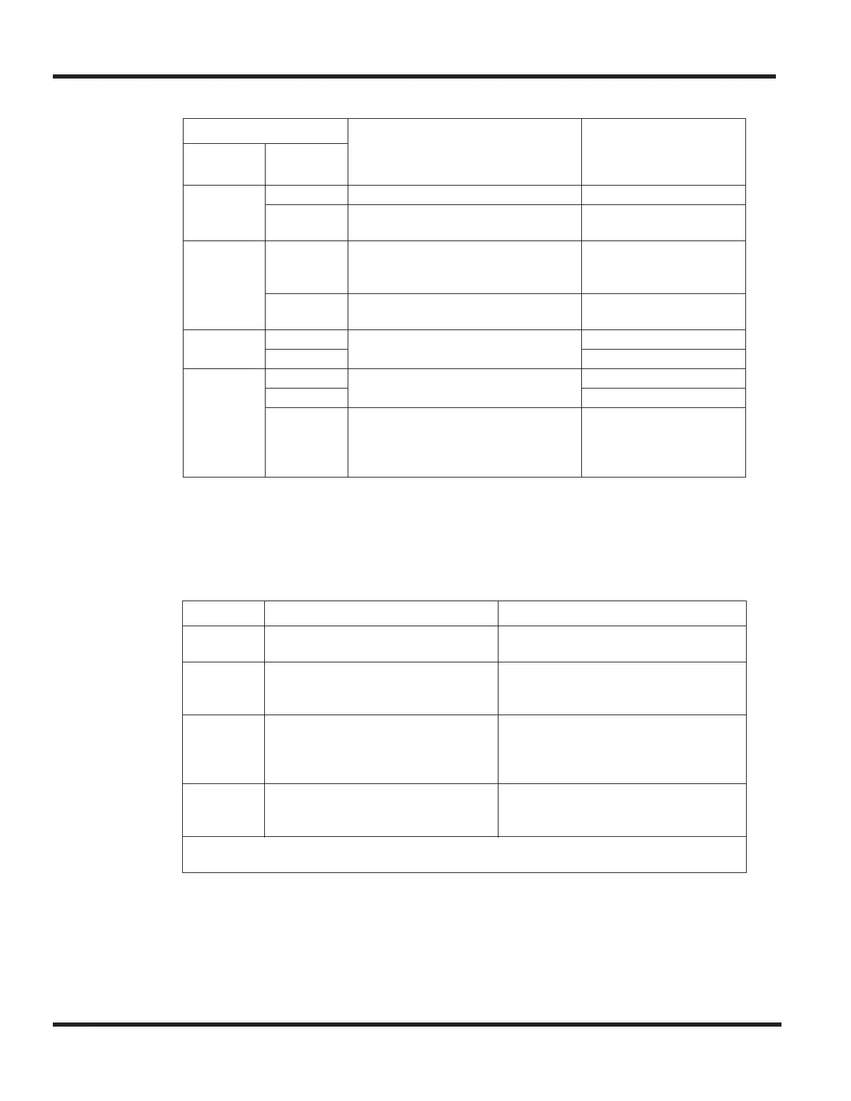
2.7.7.1 LED Indications
In addition to the above LED indications, the LEDs will also indicate alarm information for Layer 1
issues. In normal operating mode, the UX5000 controls the LEDs on each blade. However, if an
alarm indication occurs, the T1 blade will control the LEDs for the blade. When a Layer 1 alarm is
detected, the T1 blade will flash red-green-red-green followed by another LED indication as
described below. This 3.8 second LED cycle will continue to repeat until the issue is resolved.
LED Indication
Operation Status Operation Status
Live LED
(green)
Busy LED
(red)
On On Blade initializing
Flashing
(100 ms)
Boot program starting
Flashing
(1 second)
On Blade assignment refused (system
capacity exceeded or software
version incorrect)
Flashing
(1 second)
Trouble found during self-
diagnostics routine.
Flashing
(100 ms)
On Normal operation At least 1 channel busy
Off All channels idle
Off On Blocked blade At least 1 channel busy
Off All channels idle
Flashing
(80 ms
on/off x3 /
400ms off)
Downloading firmware
Alarm Alarm Details LED Pattern
LOS LOS = Loss of Signal (Red Alarm)
No Signal (Analog Interface)
Alarm LED: red-green-red-green
then LOS LED: long red
AIS AIS = Alarm Indication Signal
(Blue Alarm)
Alarm LED: red-green-red-green
then AIS LED: red flashes on and off
slowly twice
OOF OOF = Out of Frame (Red Alarm) Alarm LED: red-green-red-green
then OOF LED: red and green LED
flash on and off 3 times at the same
time
RAI RAI = Remote Alarm Indication
(Yellow Alarm)
Alarm LED: red-green-red-green
then RAI LED: green LED flashes on
and off twice
Note: If there are multiple alarms, the highest priority alarm is indicated.
The priority order is: LOS - AIS - OOF - RAI.

 Loading...


