133
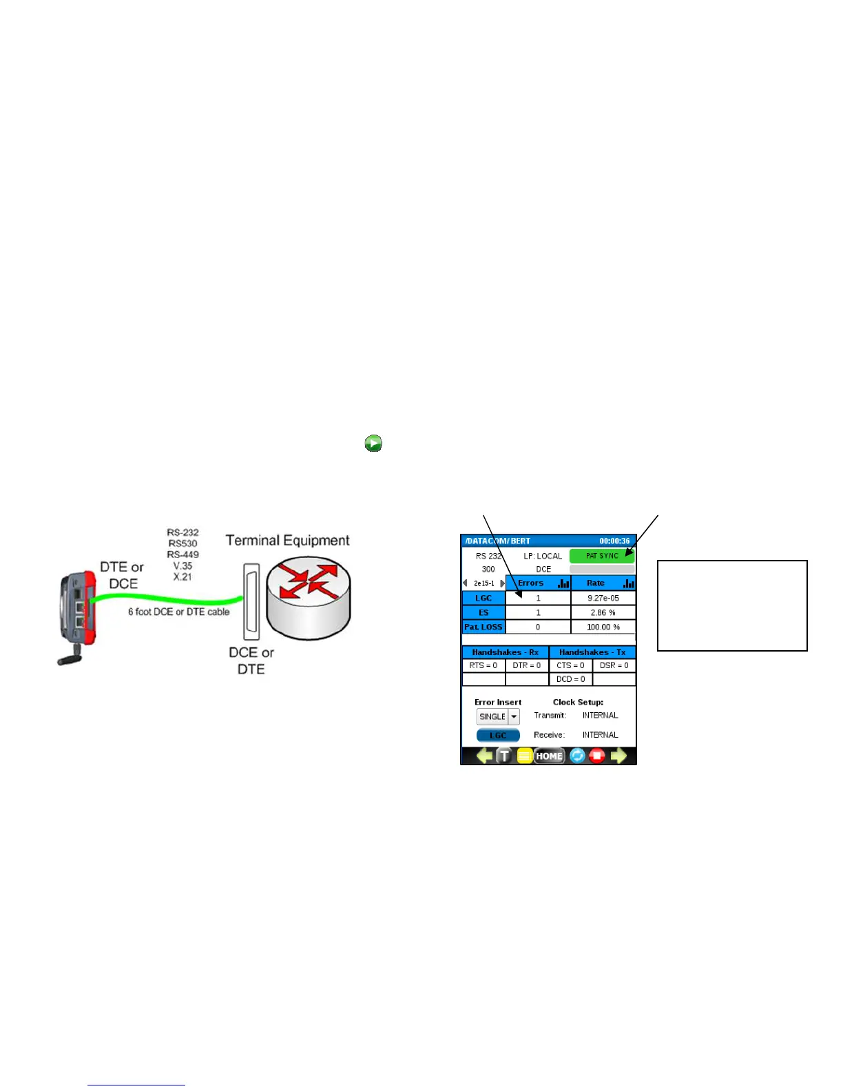
A typical loop around or point-to-point Bit Error Test setup is shown below.
If the tested device is a DCE device, set EX Mode to DTE and use the DTE datacom cable. If the tested device is a DTE
device, set EX Mode to DCE and use the DCE datacom cable.
After the datacom cable connection is made, press
to start the BERT test.
Pattern Sync LED turns Green when
the transmitted pattern matches the
When errors are detected, the
LOGIC (LGC) ERROR counter will
increment.