+/GPIO CONNECTOR
This is a 37-pin D-Sub connector used for general purpose, digital
Input/Output signals. A variety of commands are available to control
these ports. See Section 3, Remote Mode and Appendix C for
Connector Pin Outs.
RS232-C
GPIO
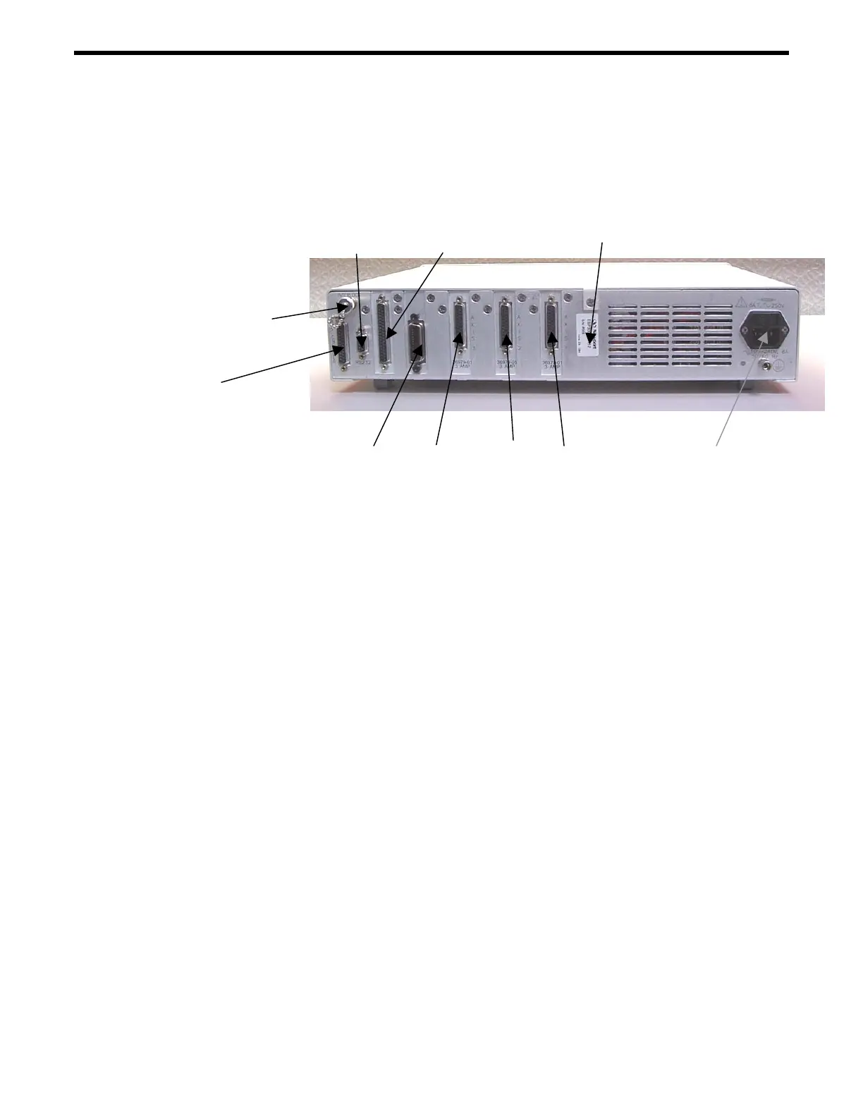
Serial No. Label
Power Entry
Module
Axis 3 Axis 2 Axis 1
Axis Connectors
IEEE-488 (optional)
AUX Encoder
Motor
Interlock
Figure 1.3: Rear Panel of the ESP300 (400 Watt chasse shown)
AUXILIARY ENCODER
This 25 pin D-Sub connector provides input for 3 auxiliary encoder
channels (axis 4, 5, 6). For signal description, see Section C.1.4.
These channels can be used for master-slaving (see Section 4.2),
trackball and other applications. Additionally, 4 digital I/O pins are
provided (See Section C.1.2).
MOTOR INTERLOCK CONNECTOR
The coaxial connector provides remote motor power interlock
capability. One or more external switches can be wired to remotely
inhibit the motor power in a way similar to the Stop All button on the
front panel.
The controller is shipped with a mating connector that provides the
necessary wiring to enable proper operation without an external
switch.
RS232-C CONNECTOR
The RS232-C interface to a host computer or terminal is made
through this 9 pin D-Sub connector. The pin out enables the use of an
off-the-shelf, pin-to-pin cable.
IEEE-488 CONNECTOR
1-10 Section 1 - Introduction

 Loading...


