E.3 Changing the Front Panel Option
1. Follow steps 1-3 of adding axis (See Section E.1).
2. Disconnect the 40 pin ribbon connector on the display side.
3. Remove the two screws as shown (See
Figure E.3).
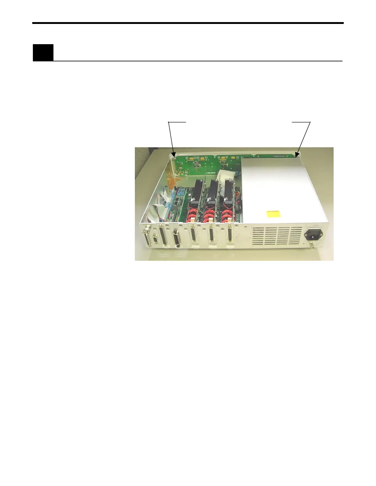
Remove the 2 screws, as shown. Remove 6
screws on the bottom of unit that attach Front
Panel to Chassis.
Figure E.3: How to remove screws inside the unit for the Front Panel
4. Remove the 6 screws on the bottom of the unit that attach the
Front Panel to the unit chassis.
5. Attach the new front panel option by installing the 6 screws on the
bottom and the two screws inside the unit.
6. Connect the front panel with the 40 pin ribbon connector.
7. Re-install the top cover.
The unit is now ready for use.
E-4 Appendix E – System Upgrades

 Loading...


