Appendix C – Connector Pin Assignments
C.1
C.1.1 GPIO Connector (37-Pin D-Sub)
ESP300 Rear Panel
This connector is dedicated to the digital I/O ports. All I/O are pulled
up to +5V DC with 4.7KΩ resistors. Maximum sink or source current
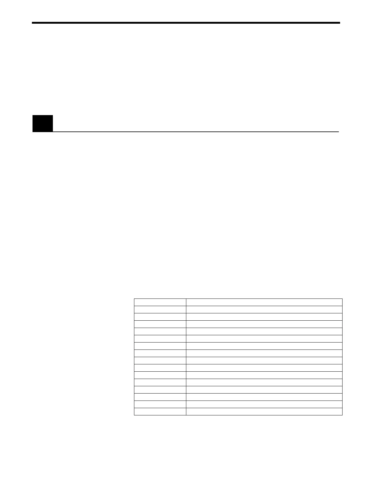
is 32 mA. Connector pin-outs are listed in
Table C.1, and
functionally described in the following paragraphs.
C.1.2 Signal Descriptions (Digital I/O, 37-Pin, JP4 Connector)
+15V supply
Digital Ground used for all digital signals.
+5V, 100mA (maximum)
+5V supply
+15V, 25mA (maximum)
Digital I/O
The digital I/O can be programmed to be either input or output (in 8-
bit blocks) via software.
DGND
Pin # Description
1 +15V, 25mA
2 +15V, 25mA
3 +5V, 100mA
4 Digital Input/Output 1
5 Digital Input/Output 2
6 Digital Input/Output 3
7 Digital Input/Output 4
8 Digital Input/Output 5
9 Digital Input/Output 6
10 Digital Input/Output 7
11 Digital Input/Output 8
12 Digital Input/Output 9
13 Digital Input/Output 10
14 Digital Input/Output 11
15 Digital Input/Output 12
Table C.1: Digital Connector Pin-Outs
Appendix C – Connector Pin Assignments C-1

 Loading...


