FRONT PANEL DISPLAY
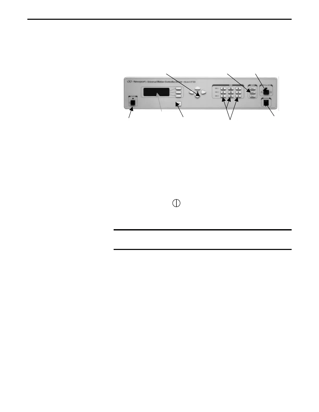
A general view of the front panel is shown in (Figure 1.2). There are
two distinct areas: a display/menu section and a motion/home section
that allows simple manual motion sequence like JOG and HOMING.
Power
Keypad
Connector
X-Y buttons
Menu
Button
Display
Window
J og Buttons
Home Buttons
Stop All Axis
Figure 1.2: ESP300 Front Panel with Displays
BLANK FRONT PANEL
This version does not provide a display or local operation.
Power Section
The black push button type switch on the lower left corner is used to
turn power On or Off . The on state is indicated with a green LED
above the push-button.
1.4.4 Rear Panel Description
NOTE
See Appendix C for pin-outs.
AXIS CONNECTORS (AXIS 1 – AXIS 3)
There are up to three 25-pin D-Sub connectors on the rear panel, one
for each axis. Unused axes have blank panels.
Section 2 – Modes of Operation 1-9

 Loading...


