This is a standard 24 pin connector to interface with a standard
IEEE-488 device.
Note:
This is an optional feature.
POWER ENTRY MODULE
The power entry section on the right side of the rear panel provides a
standard IEC 320 inlet, a fuse holder, and a binding post to ground the
controller if the main power supply wiring does not provide earth
ground terminals.
1.5 System Setup
This section guides the user through the proper set-up of the motion
control system.
Carefully unpack and visually inspect the controller and stages for
any damage.
Place all components on a flat and clean surface.
1.5.1 Line Voltage
NOTE
The controller can operate from 100-240VAC, ±10%, at a
frequency of 50/60 Hz.
1.5.2 First Power ON
Plug the AC line cord supplied with the ESP300 into the power entry
module on the rear panel.
CAUTION
Do not block AC line cord entry area for disconnecting purpose.
Plug the AC line cord into the AC wall-outlet.
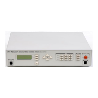
Push in the POWER switch on the lower left side of the front panel.
Shortly after the power is switched on, the ESP300 with front panel
display will perform a start-up sequence as described below.
• Momentarily display: "Newport ESP300" and the Firmware
Version
Section 2 – Modes of Operation 1-11

 Loading...