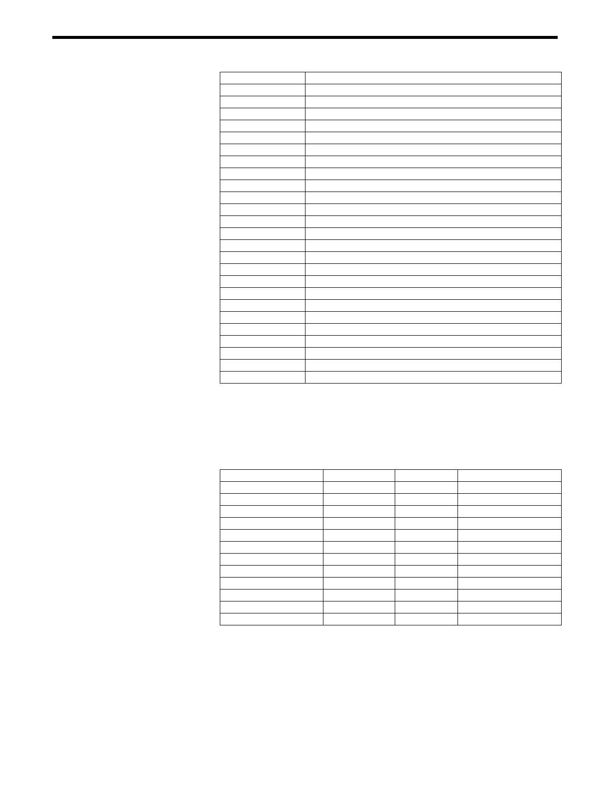
Pin # Description
1 Encoder Channel A (+), Axis 4
2 Encoder Channel A (-), Axis 4
3 Encoder Channel B (+), Axis 4
4 Encoder Channel B (-), Axis 4
5 Encoder Channel A (+), Axis 5
6 Encoder Channel A (-), Axis 5
7 Encoder Channel B (+), Axis 5
8 Encoder Channel B (-), Axis 5
9 Encoder Channel A (+), Axis 6
10 Encoder Channel A (-), Axis 6
11 N/C
12 N/C
13 N/C
14 Encoder Channel B (+), Axis 6
15 Encoder Channel B (-), Axis 6
16 Digital Input/Output 0
17 Digital Input/Output 1
18 Digital Input/Output 2
19 Digital Input/Output 3
20 +5V (500 mA max)
21 +5V (500 mA max)
22 DGND
23 DGND
24 N/C
25 N/C
Table C.3: Auxiliary Encoder Connector Pin-Outs
C.1.6 IEEE-488 Interface Connector (24 Pin)
The IEEE488 Interface Connector has a standard configuration, as
shown in
Table C.4.
Description Pin # Pin # Description
DIO1 1 13 DIO5
DIO2 2 14 DIO6
DIO3 3 15 DIO7
DIO4 4 16 DIO8
EOI 5 17 REN
DAV 6 18 GND
NRFD 7 19 GND
NDAC 8 20 GND
IFC 9 21 GND
SRQ 10 22 GND
ATN 11 23 GND
SIELD 12 24 SIGNAL GND
Table C.4: IEEE488 Interface Connector
C.1.7 RS-232C Interface Connector (9-Pin D-Sub)
The RS-232C interface uses a 9-pin sub-F connector. The back panel
connector pin-out is shown in (
Figure C.1).
C-6 Appendix C – Connector Pin Assignments

 Loading...


