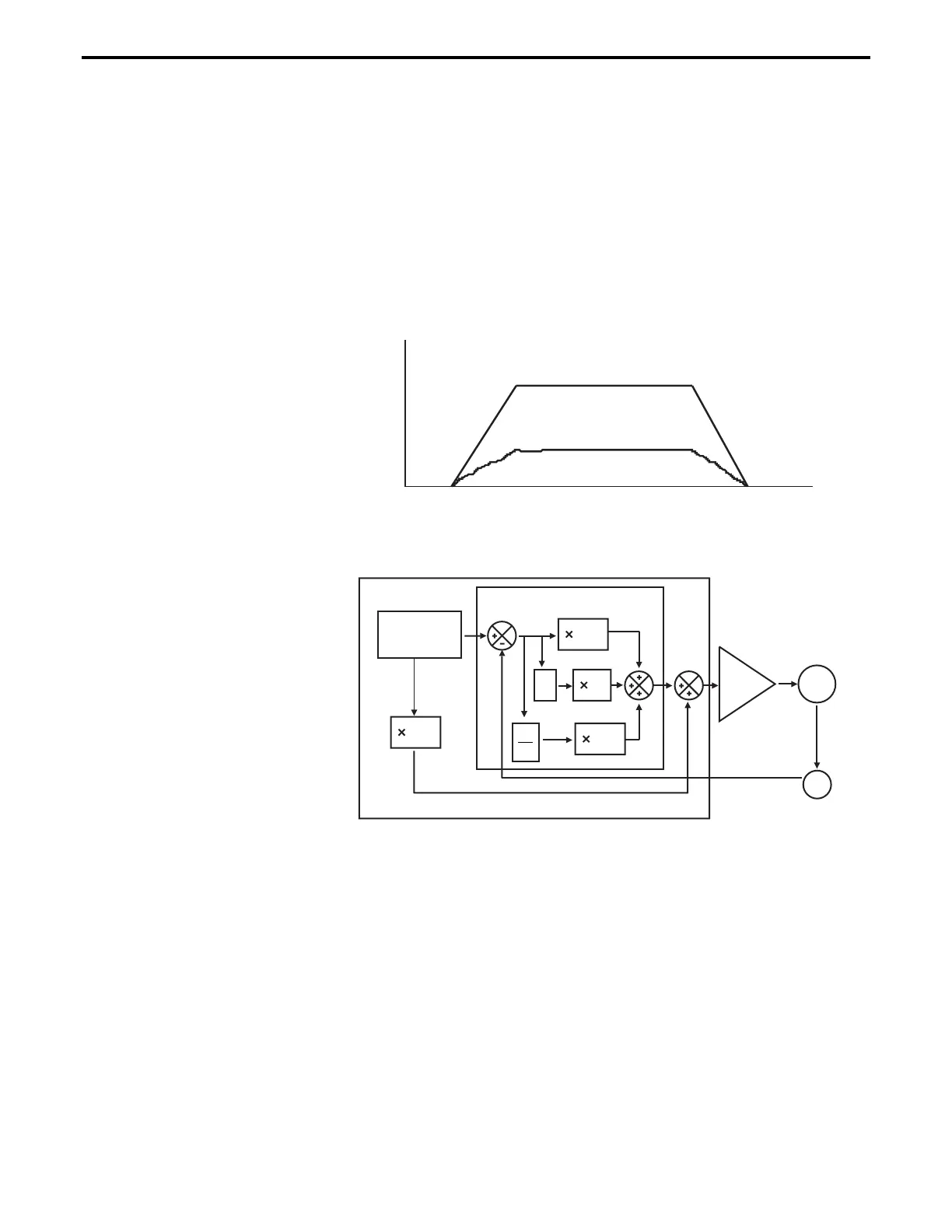
Of course, this looks like an open loop, and it is (
Figure 5.18). But,
adding this signal to the closed loop has the effect of significantly
reducing the "work" the PID has to do, thus reducing the overall
following error. The PID now has to correct only for the residual error
left over by the feed-forward signal.
Because the signal is derived from the velocity profile and it is being
sent directly to motor driver, the procedure is called velocity feed-
forward.
Figure 5.17: Trapezoidal Velocity Profile
Time
Desired Velocity
Motor Voltage
Trajectory
Generator
Motion Controller
Servo Controller
Driver
Motor
Encoder
Kp
Ki
∫
e
Kd
Kvff
de
dt
e
Figure 5.18: PID Loop with Feed-Forward
There is another special note that has to be made about the feed-
forward method. The velocity is approximately proportional to the
voltage and only for constant loads, but this true only if the driver is a
simple voltage amplifier or current (torque) driver. A special case is
when the driver has its own velocity feedback loop from a tachometer
(
Figure 5.19).
The tachometer is a device that outputs a voltage proportional with
the velocity. Using its signal, the driver can maintain the velocity to
be proportional to the control signal.
Section 5 – Motion Control Tutorial 5-17

 Loading...


