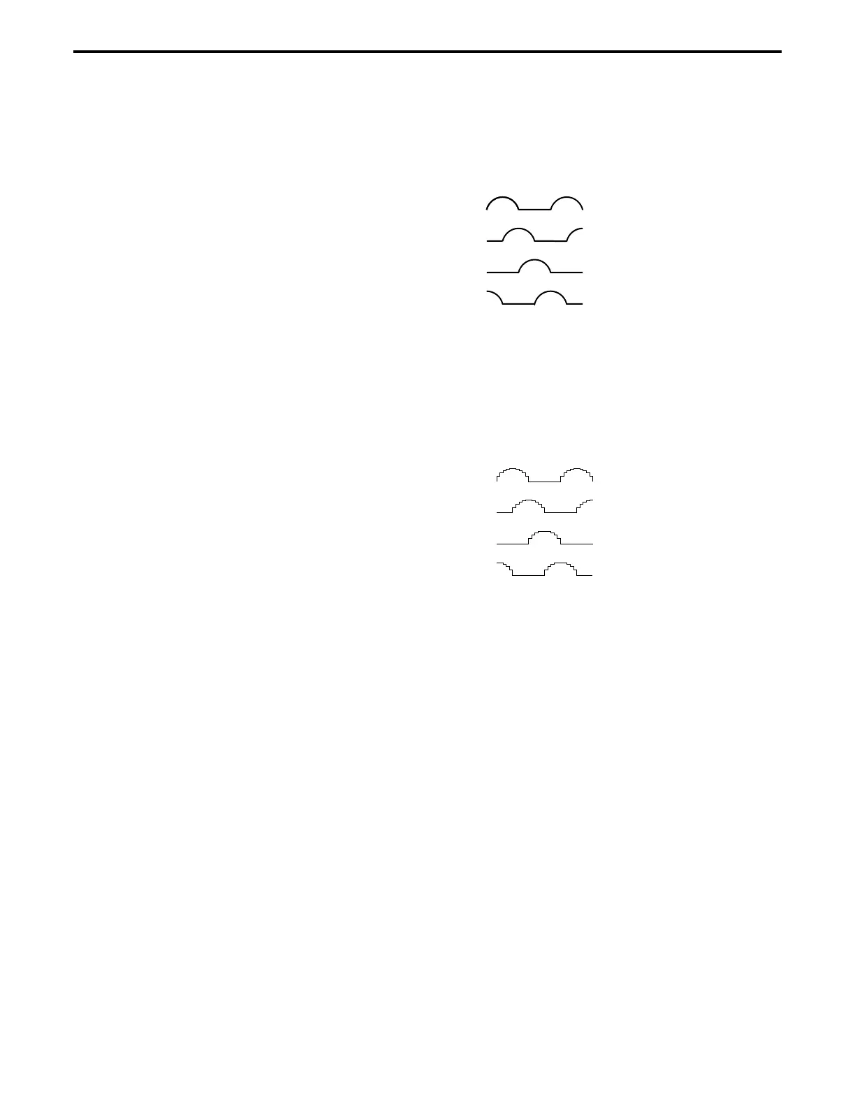
The conclusion is that, varying the ratio between the currents of the
two phases, the user can position the rotor anywhere between the two
full step locations. To do so, the user needs to drive the motor with
analog signals, similar to (
Figure 5.37).
A
B
C
D
Figure 5.37: Timing Diagram, Continuous Motion (Ideal)
But a stepper motor should be stepping. The controller needs to move
it in certain known increments. The solution is to take the halh-sine
waves and digitize them so that for every step command, the currents
change to some new pre-defined levels, causing the motor to advance
one small step (
Figure 5.38).
A
B
C
D
Figure 5.38: Timing Diagram, Mini-Stepping
This driving method is called mini-stepping or micro-stepping. For
each step command, the motor will move only a fraction of the full-
step. Motion steps are smaller so the motion resolution is increased
and the motion ripple (noise) is decreased.
However, mini-stepping comes at a price. First, the driver electronics
are significantly more complicated. Secondly, the holding torque or
one step is reduced by the mini-stepping factor. In other words, for a
x10 mini-stepping, it takes only 1/10 of the full-step holding torque to
cause the motor to have a positioning error equivalent to one step (a
mini-step).
To clarify a little what this means, lets take a look at the torque
produced by a stepper motor. For simplicity, lets consider the case of
a single phase being energized (
Figure 5.39).
Once the closest rotor tooth has been pulled in, assuming that the user
doesn't have any external load, the motor does not develop any
torque. This is a stable point.
Section 5 – Motion Control Tutorial 5-29

 Loading...


