4. Insert the driver module for the respective axis. The connector of
the driver module is keyed to prevent insertion with improper
polarity. Make sure the keys line up properly before you try to
insert the module (See
Figure E.2).
5. Attach the driver panel to the rear panel of the unit with the two
supplied screws.
6. Re-install the top cover.
The unit is now ready for use.
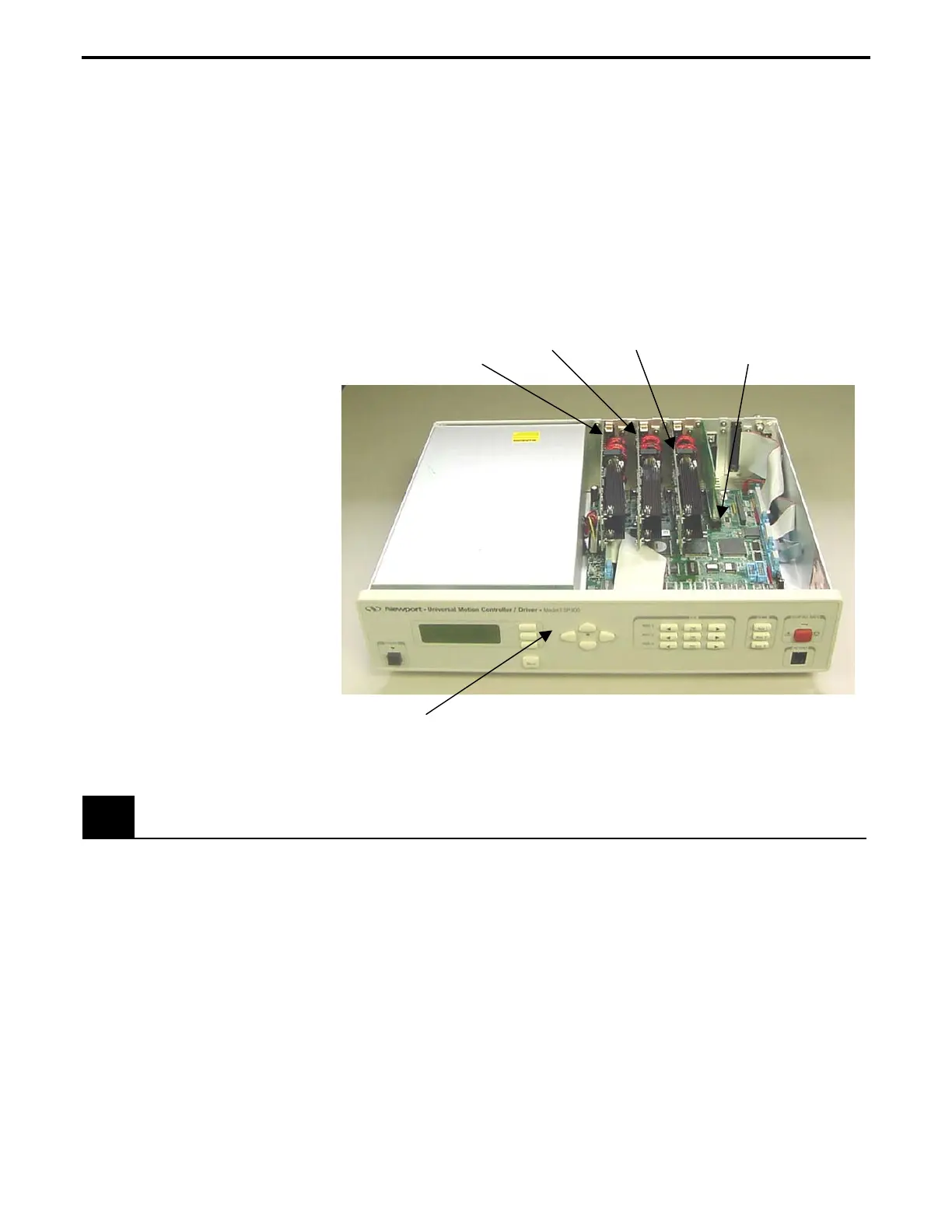
Axis 1 Axis 2 Axis 3
IEEE-488 Driver Module
Front Panel
Figure E.2: Interior of the unit explaining the connectors
E.2 Adding IEEE488
1. Follow steps 1 – 3 adding axes.
2. Insert the IEEE-488 driver module in the connector. The
connector of the module is keyed to prevent insertion with
improper polarity. Make sure the keys line up properly before you
try to insert the module.
3. Attach the IEEE-488 panel to the rear panel of the unit with the
two supplied screws.
4. Re-install the top cover.
The unit is now ready for use.
Appendix E – System Upgrades E-3

 Loading...


