Training Guide Course No. 196514
Level 2 Maintenance, X-1000 Series Dispensing Systems 4-9 P/N 196515 (Revision A)
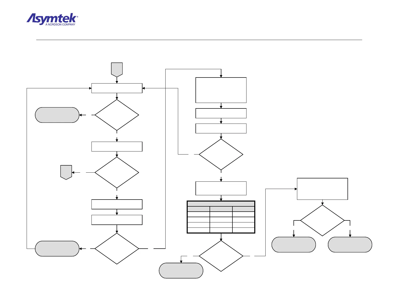
A
Are the green 5V,
A+15V, and A+5V
LEDs illuminated?
Replace fuse and repeat
indicated steps
Locate the power LEDs on the
XY Servo Interface PWA.
Locate the power LEDs on the
Main Interface PWA.
Are the green 5V,
A+15V, and A+5V
LEDs illuminated?
Switch the Main Circuit Breaker
to the OFF (0) position.
Check continuity of the fuses on
the Main Interface PWA.
Do the fuses have
continuity?
No
No Main Power Fault. If it
reoccurs, contact Asymtek
Technical Support.
No
No
Verify the DC Power Cable (P/N
193326) is securely connected
between the Computer Interface
PWA Power Terminal and J2
labeled DC POWER IN on the
Main Interface PWA.
Switch the Main Circuit Breaker
to the ON (I) position.
Locate the power LEDs on the
Main Interface PWA.
Are the green
+5V, +12V, -12V, and
A+5V LEDs
illuminated?
Yes
GroundBlack5
-12VWhite4
+12VOrange3
+5VRed2
VDCWire ColorPin Number
TABLE 1
Measure VDC of DC Power
Cable (P/N 193326) at J2 on Main
Interface PWA (See Table 1)
No
Are the readings in
accordance with the
above table?
Main Interface PWA
(P/N 60-1200-00) has
failed.
Yes
Measure VDC from cable
terminal on the Computer
Interface Board (each wire clamp
of the Cable Terminal is labeled
with the VDC value).
Are VDC readings
same as specified on
labels for cable
terminal wire
clamps?
B
Yes
Yes
No
DC Power Cable
(P/N 193326) has failed
Computer
(P/N 62-1632-00) has
failed.
Yes No
Yes
A
Are the green 5V,
A+15V, and A+5V
LEDs illuminated?
Are the green 5V,
A+15V, and A+5V
LEDs illuminated?
Replace fuse and repeat
indicated steps
Locate the power LEDs on the
XY Servo Interface PWA.
Locate the power LEDs on the
Main Interface PWA.
Are the green 5V,
A+15V, and A+5V
LEDs illuminated?
Are the green 5V,
A+15V, and A+5V
LEDs illuminated?
Switch the Main Circuit Breaker
to the OFF (0) position.
Check continuity of the fuses on
the Main Interface PWA.
Do the fuses have
continuity?
Do the fuses have
continuity?
No
No Main Power Fault. If it
reoccurs, contact Asymtek
Technical Support.
No
No
Verify the DC Power Cable (P/N
193326) is securely connected
between the Computer Interface
PWA Power Terminal and J2
labeled DC POWER IN on the
Main Interface PWA.
Switch the Main Circuit Breaker
to the ON (I) position.
Locate the power LEDs on the
Main Interface PWA.
Are the green
+5V, +12V, -12V, and
A+5V LEDs
illuminated?
Are the green
+5V, +12V, -12V, and
A+5V LEDs
illuminated?
Yes
GroundBlack5
-12VWhite4
+12VOrange3
+5VRed2
VDCWire ColorPin Number
TABLE 1
GroundBlack5
-12VWhite4
+12VOrange3
+5VRed2
VDCWire ColorPin Number
TABLE 1
Measure VDC of DC Power
Cable (P/N 193326) at J2 on Main
Interface PWA (See Table 1)
No
Are the readings in
accordance with the
above table?
Are the readings in
accordance with the
above table?
Main Interface PWA
(P/N 60-1200-00) has
failed.
Yes
Measure VDC from cable
terminal on the Computer
Interface Board (each wire clamp
of the Cable Terminal is labeled
with the VDC value).
Are VDC readings
same as specified on
labels for cable
terminal wire
clamps?
Are VDC readings
same as specified on
labels for cable
terminal wire
clamps?
B
Yes
Yes
No
DC Power Cable
(P/N 193326) has failed
Computer
(P/N 62-1632-00) has
failed.
Yes No
Yes
Diagram Sheet 4-2-2
Main Power Fault Isolation Procedure – Main Power Verification (Continued)
 Loading...


