Training Guide Course No. 196514
Level 2 Maintenance, X-1000 Series Dispensing Systems 4-10 P/N 196515 (Revision A)
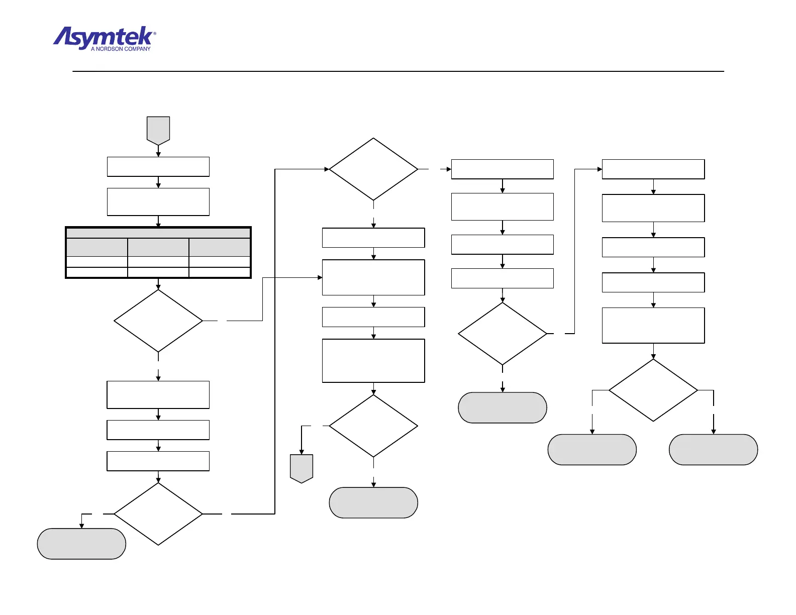
Are the green 5V,
A+15V, and A+5V
LEDs illuminated?
Are the green 5V,
A+15V, and A+5V
LEDs illuminated?
B
Switch the Main Circuit Breaker
to the OFF (0) position.
Visually inspect the Cables listed
in Table 2 for damage and
correct connections.
J29J1006-4525-00
J26J1806-4530-00
Main Interface
Location
XY Servo Interface
Location
Cable Part Number
TABLE 2
J29J1006-4525-00
J26J1806-4530-00
Main Interface
Location
XY Servo Interface
Location
Cable Part Number
TABLE 2
Are the Cables
damaged or improperly
connected?
Are the Cables
damaged or improperly
connected?
Correct Cable connection.
If damaged, replace Cable(s)
(P/N 06-4530-00, 06-4525-00).
Yes
Switch the Main Circuit Breaker
to the ON (I) position.
Locate the power LEDs on the
XY Servo Interface PWA.
Damaged or improperly
connected cable is root
cause of fault.
Yes
Are the green
A+15V, and A+5V
LEDs illuminated?
Are the green
A+15V, and A+5V
LEDs illuminated?
Switch the Main Circuit Breaker
to the OFF (0) position.
Disconnect the Servo
Interconnect A Cable
(P/N 06-4525-00) from the
Main Interface PWA.
No
No
No
Switch the Main Circuit Breaker
to the ON (l) position.
Measure VDC at J29 (SERVO
SIGNAL INTERCONNECT A) at
Pin 36 and ground, then at Pin
33 and ground (connect ground
to Pin 37).
Is the reading
>=4 VDC
at Pin 36 and >=14
VDC at Pin 33?
Is the reading
>=4 VDC
at Pin 36 and >=14
VDC at Pin 33?
Main Interface PWA
(P/N 60-1200-00) has
failed.
No
C
Yes
Switch the Main Circuit Breaker
to the OFF (0) position.
Disconnect the XY Servo DC
Power Cable (P/N 06-4530-00)
from Main Interface PWA J26.
Switch the Main Circuit Breaker
to the ON (l) position.
Measure VDC at J26, Pin 1
(connect ground to Pin 37).
Is the reading
>=4 VDC?
Is the reading
>=4 VDC?
Main Interface PWA
(P/N 60-1200-00) has
failed.
Yes
Switch the Main Circuit Breaker
to the OFF (0) position.
Reconnect the XY Servo DC
Power Cable (P/N 06-4530-00)
to the Main Interface PWA.
Switch the Main Circuit Breake
to the ON (I) position.
Locate J18 on the XY
Servo Interface PWA.
With the XY Servo DC Power
Cable connected to the Main
Interface PWA, measure VDC at
Pin 1 (connect ground to Pin 4).
Is the reading
>=4 VDC?
Is the reading
>=4 VDC?
No
Yes
LED on the XY Servo
Interface PWA
(P/N 60-1211-00) has
failed
XY Servo DC Power Cable
(P/N 06-4530-00) has
failed.
Yes No
Diagram Sheet 4-2-3
Main Power Fault Isolation Procedure – Main Power Verification (Continued)
 Loading...


