Training Guide Course No. 196514
Level 2 Maintenance, X-1000 Series Dispensing Systems 4-13 P/N 196515 (Revision A)
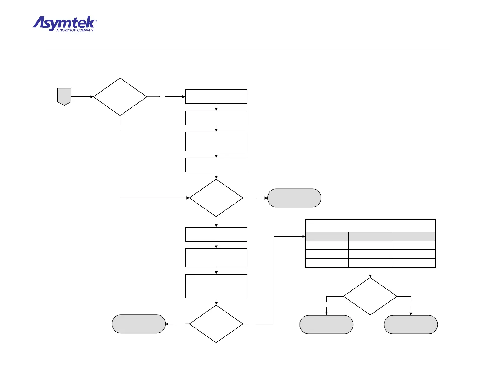
Switch the Main Circuit Breaker
to the OFF (0) position.
Are the cables
connected to the
Power Manager as
specified?
Are the cables
connected to the
Power Manager as
specified?
Cables are root cause of
system power fault.
Order and connect proper
cables to Power Manager.
Power-up the Power Manager
by switching the Main Circuit
Breaker to the ON (I) position.
Press the green ON (I) button
on the Operator's Console.
Does the green
ON (I) button on
Operator's Console
illuminate?
Does the green
ON (I) button on
Operator's Console
illuminate?
Switch the Main Circuit Breaker
to the OFF (0) position.
Verify the green ON (I) button is
assembled and connected to
Cable P/N 06-4515-00.
Check continuity between Pin 1
(black wire) and Pin 3 (red wire)
at the green ON (I) button
harness connector.
Is there
continuity between Pin
1 (black wire) and Pin
3 (red wire)?
Is there
continuity between Pin
1 (black wire) and Pin
3 (red wire)?
Go to Cable Verification
Procedure
Pin 6Brown to BluePin 3
Pin 4Red to GreenPin 2
Pin 2Black to WhitePin 1
Cable Connector
P/N 06-4515-00
Wire Color
Start Button
Harness Connector
Press the green ON (1) button on the Operators Console and check the continuity
of the green ON (1) button at the cable connector as specified below:
Pin 6Brown to BluePin 3
Pin 4Red to GreenPin 2
Pin 2Black to WhitePin 1
Cable Connector
P/N 06-4515-00
Wire Color
Start Button
Harness Connector
Press the green ON (1) button on the Operators Console and check the continuity
of the green ON (1) button at the cable connector as specified below:
Is there
continuity between Pin
1 (black wire) and Pin
3 (red wire)?
Is there
continuity between Pin
1 (black wire) and Pin
3 (red wire)?
Power Manager (P/N 62-
1620-01) has failed.
ON (I) Switch
(P/N 40-2484) has failed
A
No
Yes
Yes
No
Yes
No
Yes No
Diagram Sheet 4-2-6
System Power Fault Isolation Procedure - System Power Verification (Continued)
 Loading...


