Training Guide Course No. 196514
Level 2 Maintenance, X-1000 Series Dispensing Systems 4-14 P/N 196515 (Revision A)
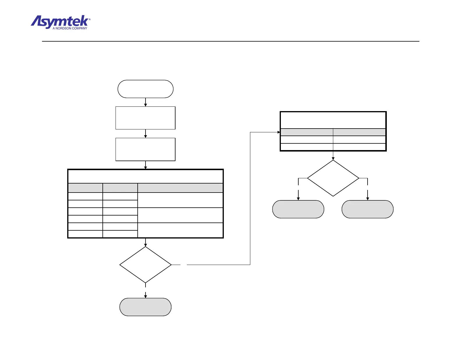
Follow steps under "No
Continuity" in table above.
Is there continuity
between the pins
specified above?
Is there continuity
between the pins
specified above?
Disconnect Cable (P/N 06-
4515-00) from the Power
Control outlet of the Power
Manager.
Verify the Cable is connected
to front EMO Button, black
OFF (0) button, and green
ON (I) button.
Is there continuity
between the pins
specified above?
Is there continuity
between the pins
specified above?
Go to Rear EMO Button
Verification procedure.
Power Manager (P/N 62-
1620-01) has failed.
Rear EMO/VentPin 3 to Pin 6
Rear EMO/VentPin 2 to Pin 4
Activation Component
Power Control Connector (J5)
Check continuity of pins specified below at Power Manager Power
Control connector J5.
Rear EMO/VentPin 3 to Pin 6
Rear EMO/VentPin 2 to Pin 4
Activation Component
Power Control Connector (J5)
Check continuity of pins specified below at Power Manager Power
Control connector J5.
Switch the Main Circuit
Breaker to the OFF (0)
position.
ON (1) ButtonPin 10 to Pin 11
Go to System Power Verification in System Power Fault
Isolation Procedure. The green ON (1) button must be
pressed for continuity check.
ON (1) ButtonPin 8 to Pin 9
OFF (0) ButtonPin 6 to Pin 7
Go to Operator’s Console OFF (0) Button Verification.
OFF (0) ButtonPin 4 to Pin 5
Front EMOPin 1 to Pin 3
Go to Front EMO button Verification.
Front EMOPin 1 to Pin 2
If No Continuity
Component
Activation
D-Sub Connector
(P/N 06-4516-00)
Check continuity between D-Sub Connector pins as specified below:
Yes
No
Yes No
Diagram Sheet 4-2-7
System Power Fault Isolation Procedure - Power Cable Verification
 Loading...


