Training Guide Course No. 196514
Level 2 Maintenance, X-1000 Series Dispensing Systems 4-20 P/N 196515 (Revision A)
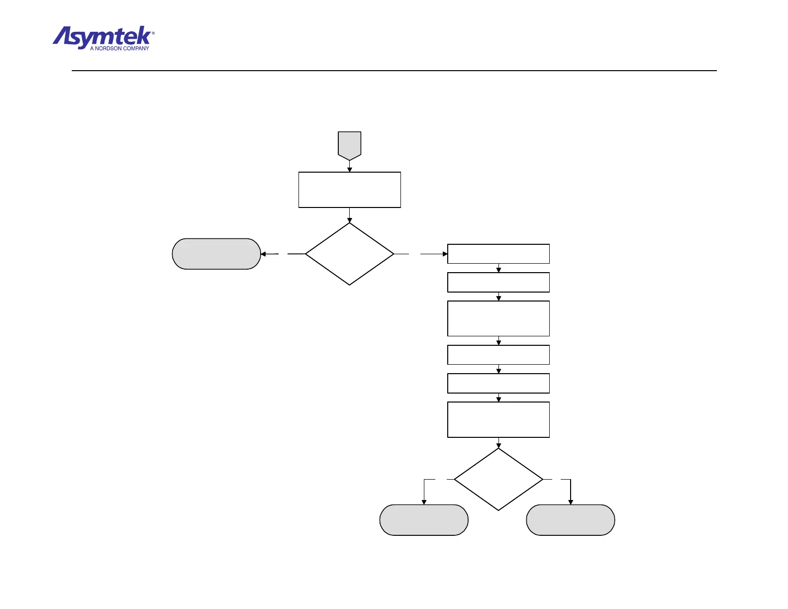
Measure VDC between test
points TP7 (+24V), and TP6
(Return) on the XY Servo
Interface PWA.
XY Servo Interface PWA
(P/N 60-1211-00) has
failed.
Is the reading greater
than 23 VDC?
Cable (P/N 06-4530-00)
has failed.
Is the reading greater
than 23 VDC?
Press the black OFF (0) button
on the Operator's Console.
A
Main Interface PWA (P/N
60-1200-00) has failed
Switch the Main Circuit Breaker
to the OFF (0) position.
Measure VDC between test
points TP7 (+24V), and TP6
(Return) on the XY Servo
Interface PWA.
Reconnect the DC Power Cable
(P/N 06-4530-00) to the Main
Interface Board XY Servo DC
Power connector.
Press the green ON (I) button on
the Operator's Console.
Switch the Main Circuit Breaker
to the ON (I) position.
Yes No
YesNo
Measure VDC between test
points TP7 (+24V), and TP6
(Return) on the XY Servo
Interface PWA.
XY Servo Interface PWA
(P/N 60-1211-00) has
failed.
Is the reading greater
than 23 VDC?
Is the reading greater
than 23 VDC?
Cable (P/N 06-4530-00)
has failed.
Is the reading greater
than 23 VDC?
Is the reading greater
than 23 VDC?
Press the black OFF (0) button
on the Operator's Console.
A
Main Interface PWA (P/N
60-1200-00) has failed
Switch the Main Circuit Breaker
to the OFF (0) position.
Measure VDC between test
points TP7 (+24V), and TP6
(Return) on the XY Servo
Interface PWA.
Reconnect the DC Power Cable
(P/N 06-4530-00) to the Main
Interface Board XY Servo DC
Power connector.
Press the green ON (I) button on
the Operator's Console.
Switch the Main Circuit Breaker
to the ON (I) position.
Yes No
YesNo
Diagram Sheet 4-2-13
System Power Fault Isolation Procedure - XY Servo Power Verification Procedure (Continued)
 Loading...


