Training Guide Course No. 196514
Level 2 Maintenance, X-1000 Series Dispensing Systems 4-134 P/N 196515 (Revision A)
Measure the VDC at Pin 3 and
test point
TP 2 while the Height
Sensor probe is Disarmed (up)
and when it is Armed (down).
Is reading 5 VDC
for Armed state and 0
VDC for Disarmed
state?
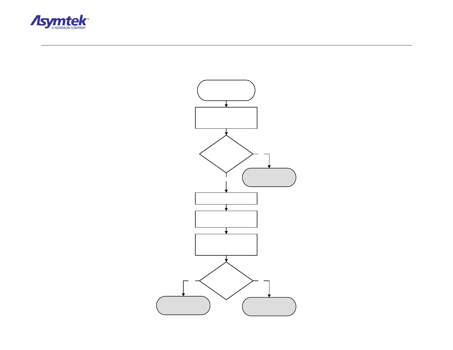
Locate U22 on the Main
Interface PWA.
Locate Connector J5 on the Main
Interface PWA.
Ensure that Ribbon Cable (P/N
19332) is securely connected to
the PIO 96 Board.
Measure the VDC at Pin 15 and
test point TP 2 while the Height
Sensor probe is Disarmed (up)
and when it is Armed (down).
The PIO 96 Card (P/N 59-
6070) has failed.
Is reading 5 VDC
for Armed state and 0
VDC for Disarmed
state?
Contact Asymtek
Technical Support
Contact Asymtek
Technical Support
Yes
No
Yes
No
Measure the VDC at Pin 3 and
test point
TP 2 while the Height
Sensor probe is Disarmed (up)
and when it is Armed (down).
Is reading 5 VDC
for Armed state and 0
VDC for Disarmed
state?
Is reading 5 VDC
for Armed state and 0
VDC for Disarmed
state?
Locate U22 on the Main
Interface PWA.
Locate Connector J5 on the Main
Interface PWA.
Ensure that Ribbon Cable (P/N
19332) is securely connected to
the PIO 96 Board.
Measure the VDC at Pin 15 and
test point TP 2 while the Height
Sensor probe is Disarmed (up)
and when it is Armed (down).
The PIO 96 Card (P/N 59-
6070) has failed.
Is reading 5 VDC
for Armed state and 0
VDC for Disarmed
state?
Is reading 5 VDC
for Armed state and 0
VDC for Disarmed
state?
Contact Asymtek
Technical Support
Contact Asymtek
Technical Support
Yes
No
Yes
No
Diagram Sheet 4-10-5
Height Sensor Fault Isolation Procedure – Height Sensor PIO 96 Signal Verification
 Loading...


