130
Word PageDescriptionBit
n+16 X-axis
Status
00 Reference Origin
1 Within the in-position range of the
reference origin.
170
Flags
0 Outside the in-position range of the
reference origin.
01 Busy Flag
1 A manual command is being executed.
170
0 Other than the above.
02 Servo Lock ON
1 Servo lock status
171
0 Servo free status
03 No Origin Flag
1 No origin (The reference origin isn’t fixed.)
171
0 The reference origin is fixed.
04 Axis Operating
1 There is an axis movement command.
172
0 There isn’t an axis movement command.
05 Positioning Completed
1 Within the in-position range
173
0 Outside the in-position range
06 Error Counter Alarm
1 The number of accumulated pulses in the
error counter exceeds the error counter
warning value.
173
0 Other than the above.
07 Alarm Input
1 The driver alarm input is ON.
174
0 The driver alarm input is OFF.
08 Zone 1 Flag
1 Within zone 1.
174
0 Outside of zone 1.
09 Zone 2 Flag
1 Within zone 2.
0 Outside of zone 2.
10 Zone 3 Flag
1 Within zone 3.
0 Outside of zone 3.
11 Zone 4 Flag
1 Within zone 4.
0 Outside of zone 4.
12 Zone 5 Flag
1 Within zone 5.
0 Outside of zone 5.
13 Zone 6 Flag
1 Within zone 6.
0 Outside of zone 6.
14 Zone 7 Flag
1 Within zone 7.
0 Outside of zone 7.
15 Zone 8 Flag
1 Within zone 8.
0 Outside of zone 8.
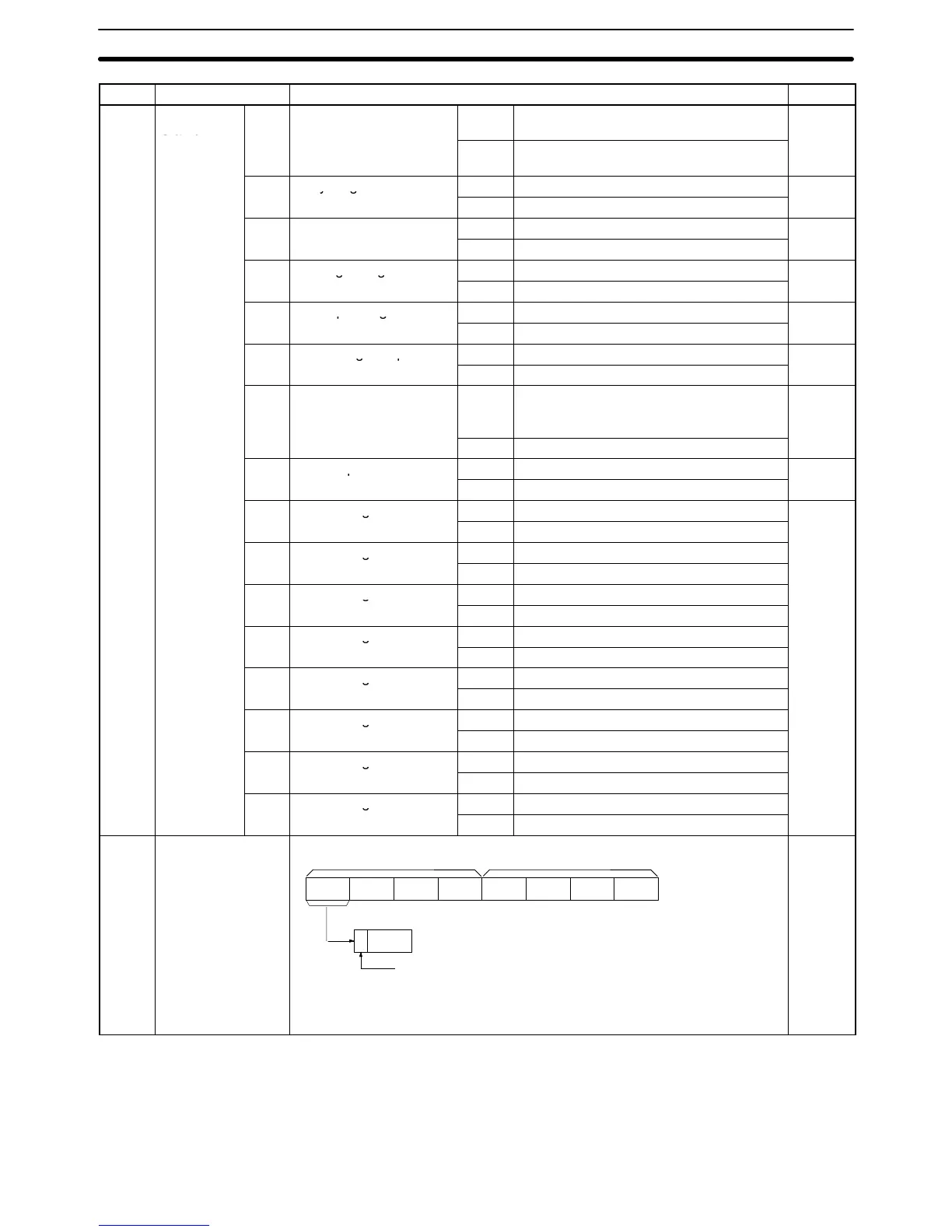
n+17
n+18
00 to 15 Y-axis current position –39,999,999 to 39,999,999 (8-digit BCD)
Remarks The current position of the reference coordinate system is output
with a decimal point set with the system parameters.
x10
4
x10
5
x10
6
x10
7
x10
0
x10
1
x10
2
x10
3
n+18 n+17
x10
7
3 2 1 0 bit
Sign bit
0: Positive
1: Negative
---
Interface Bits
Section 6-4
 Loading...


