199
High-speed Counter Board Section 8-1
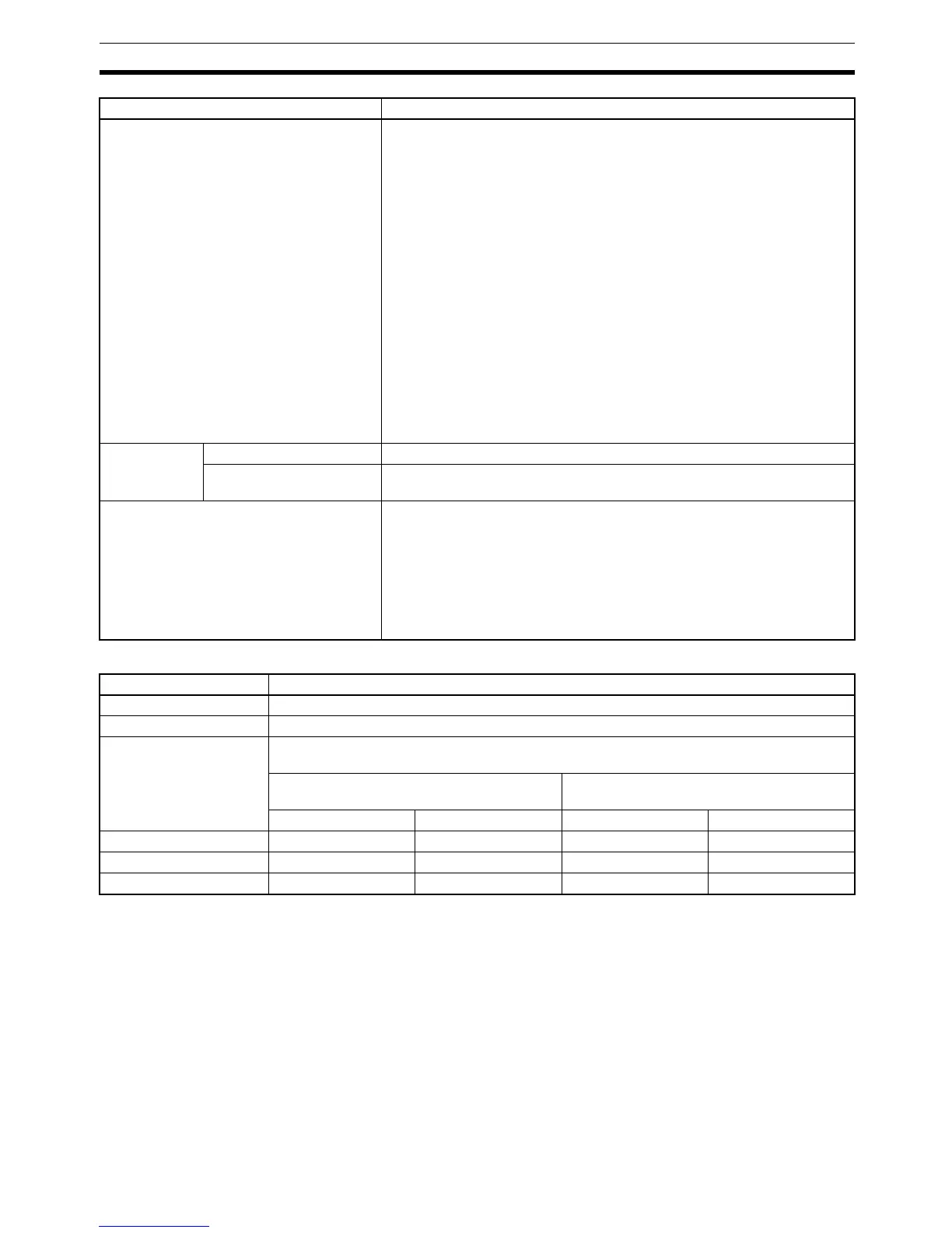
Pulse Input Specifications
Storage location of counter PV When mounted in slot 1:
Port 1: IR 201 (leftmost digits) and IR 200 (rightmost digits)
Port 2: IR 203 (leftmost digits) and IR 202 (rightmost digits)
Port 3: IR 205 (leftmost digits) and IR 204 (rightmost digits)
Port 4: IR 207 (leftmost digits) and IR 206 (rightmost digits)
When mounted in slot 2:
Port 1: IR 233 (leftmost digits) and IR 232 (rightmost digits)
Port 2: IR 235 (leftmost digits) and IR 234 (rightmost digits)
Port 3: IR 237 (leftmost digits) and IR 236 (rightmost digits)
Port 4: IR 239 (leftmost digits) and IR 238 (rightmost digits)
Data format: 8-digit BCD or 8-digit Hex
(Set in the PC Setup: Bits 00 to 03 of DM 6602/DM 6611.)
Linear Mode:
F8388608 to 8388607 BCD (Leftmost digit is F Hex for negative numbers.)
F8000000 to 07FFFFFF Hex
Ring Mode:
00000000 to 08388607 BCD
00000000 to 07FFFFFF Hex
Control
method
Target value match Up to 48 target values and external/internal output bit patterns registered.
Range comparison Up to 16 upper limits, lower limits, and external/internal output bit patterns
registered.
Counter reset method Phase-Z Signal + Software Reset
A counter is reset on the first phase-Z signal input after its Reset Bit (see
below) is turned ON.
Software Reset
A counter is reset when its Reset Bit (see below) is turned ON.
Reset Bits
IR 21200 to IR 21203 (For ports 1 to 4 in slot 1)
AR 0500 to AR 0503 (For ports 1 to 4 in slot 2)
Item Specifications
Item Specifications
Number of pulse inputs 4 inputs (Ports 1 to 4 = High-speed counters 1 to 4)
Signals Encoder inputs A and B; pulse input Z
Input voltage Switched by means of input voltage switch on the Board
(Specified separately for phases A, B, and Z.)
24 V DC±10% RS-422A line driver (AM26LS31 or equiva-
lent)
Phase A and B Phase Z Phase A and B Phase Z
Input current 5 mA typical 8 mA typical 10 mA typical 13 mA typical
ON voltage 19.6 V DC min. 18.6 V DC min. --- ---
OFF voltage 4.0 V DC min. 4.0 V DC min. --- ---

 Loading...


