2-13
2-2 Wiring
2
Design
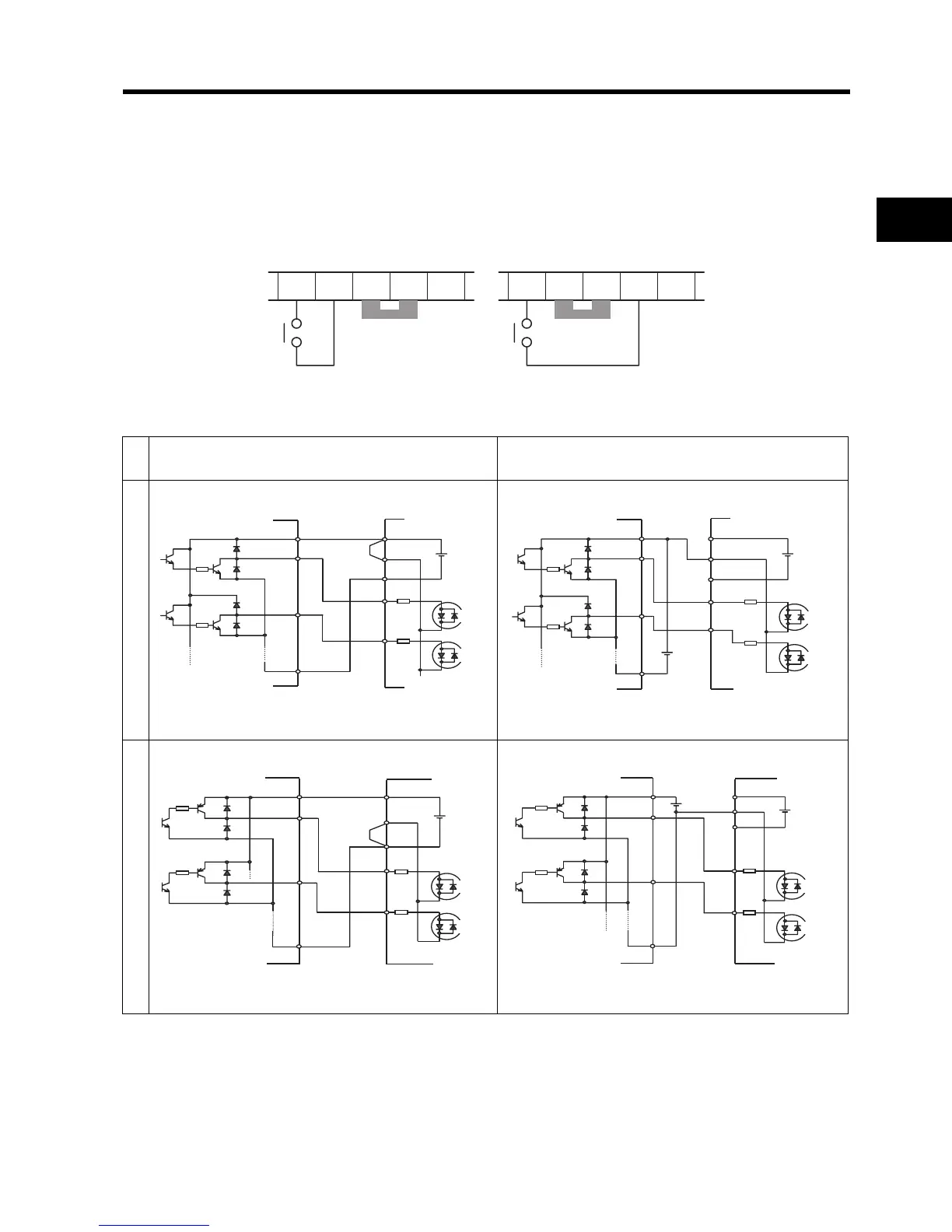
Selecting the Sequence Input Method (Sink/Source Logic)
Logic Selection Method for the Multi-function Input Terminals
When the internal power supply is used, you can switch the logic by rearranging the short-circuit bar
on the control circuit terminal block. The default setting is sink logic.
Note 1: Remove the short-circuit bar when the external power supply is used.
Inside the Inverter
When Internal interface power supply is used
When external power supply is used
Sink logicSource logic
\
1 L PCS P24 CM2
Short-circuit bar
<Sink Logic>
1 L PCS P24
CM2
Short-circuit bar
<Source Logic>
P24
PCS
L
1
5
24 V DC
Inverter
Short-circuit
bar
COM
+V
Output unit etc.
P24
PCS
L
1
5
24 V DC
Inverter
COM
DC24V
+V
Output unit etc.
P24
PCS
L
1
5
24 V DC
Inverter
Short-circuit
bar
COM
0V
Output unit etc.
P24
PCS
L
1
5
24 V DC
Inverter
COM
24 V DC
0V
Output unit etc.