1-4
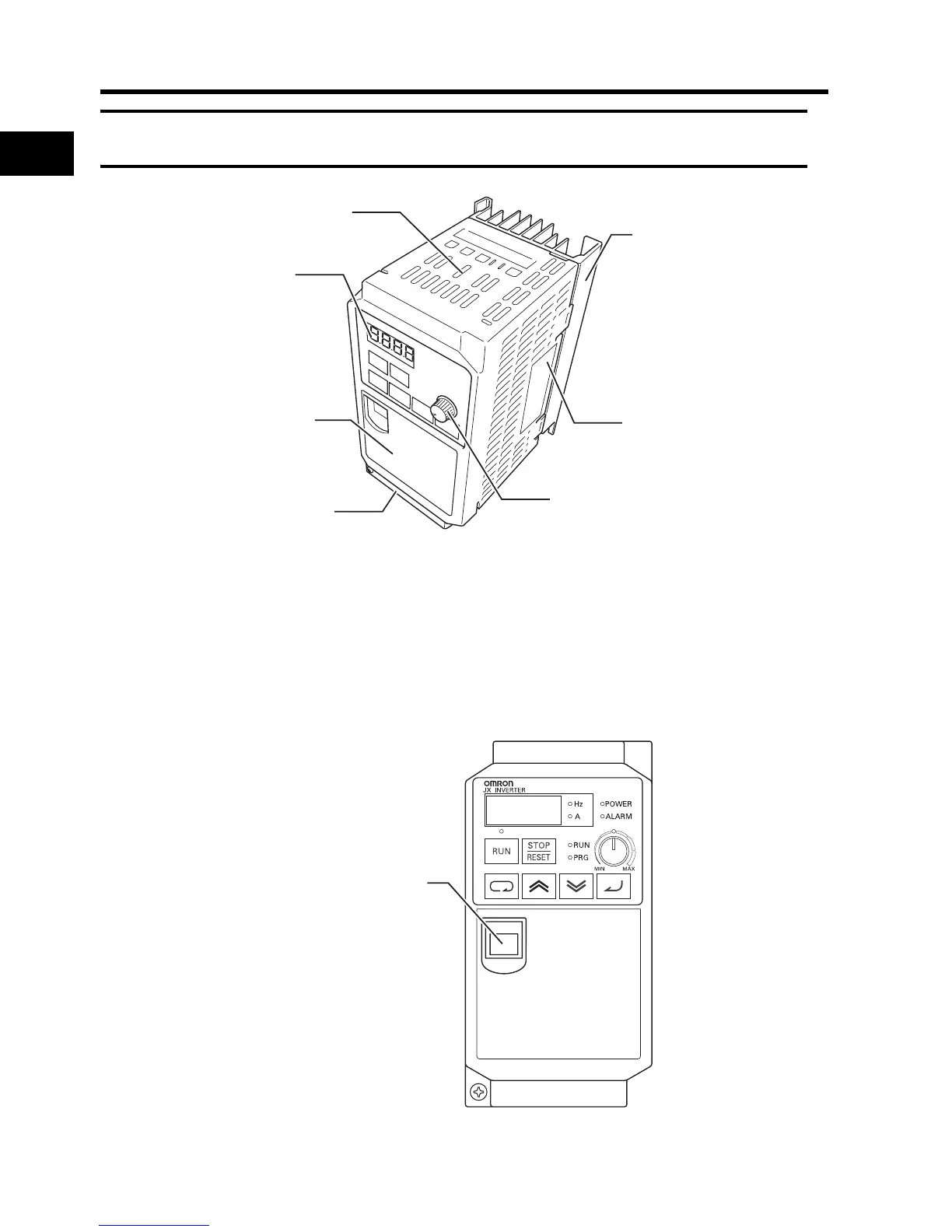
1-2 Appearance and Names of Parts
1
Overview
1-2 Appearance and Names of Parts
•The size of the fin varies with the motor capacity.
•There are two sizes depending on the motor capacity, but the fundamental structure is the same.
•Remove the front cover when connecting the power supply, the motor, and the control signal.
Connection to RJ45 Jack
Connect the communications cable after opening the cover of the communications connector.
Remove the front cover to switch communications. Refer to "Removing the Front Cover" (page 2-
7) for instructions on how to remove the front cover.
*The cover of the communications connector is removable. Remove the front cover to attach it.
Top cover
Fin
Main housing
FREQ (FREQUENCY) adjuste
Digital Operator
Front cover
Bottom cover
Communications connector
(with cover)
8888