4-55
4-2 Function Mode
4
Functions
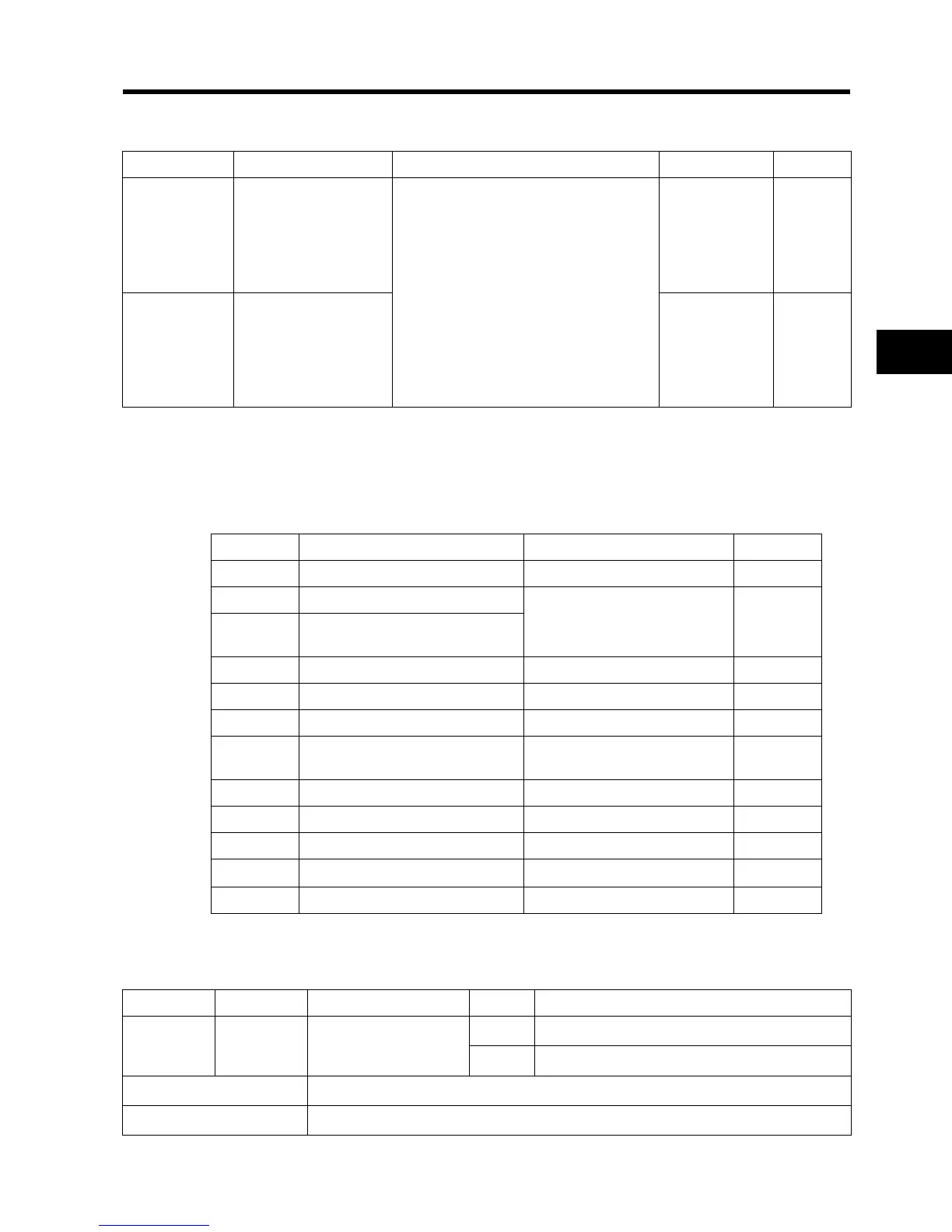
Multi-function Output Terminal Selection
•You can allocate the following functions to multi-function output terminal 11 and the relay output
terminals.
•While the multi-function output terminal 11 selection is for open collector output (allocated in
C021), the relay output (AL2, AL1) function selection is for SPDT-contact relay output (allocated in
C026).
•You can select NO- or NC-contact output for each output terminal with C031 or C036.
Signal During RUN
This function outputs a signal while the Inverter is running.
Parameter No. Function name Data Default setting Unit
C021
Multi-function output
terminal 11 selection
00: RUN (signal during RUN)
01: FA1 (constant speed arrival signal)
02: FA2 (over set frequency arrival signal)
03: OL (overload warning)
04: OD (excessive PID deviation)
05: AL (alarm output)
06: Dc (disconnection detection)
07: FBV (PID FB status output)
08: NDc (network error)
09: LOG (logic operation output)
10: ODc (Do not use.)
43: LOC (light load detection signal)
00 ⎯
C026
Relay output (AL2,
AL1) function selection
05 ⎯
Data Description Reference item Page
00 RUN: Signal during RUN Signal during RUN 4-55
01 FA1: Constant speed arrival signal
Frequency arrival signal 4-56
02
FA2: Over set frequency arrival
signal
03 OL: Overload warning Overload warning signal 4-33
04 OD: Excessive PID deviation Excessive PID deviation output 4-22
05 AL: Alarm output Alarm output 4-57
06 Dc: Disconnection detection
External analog input
disconnection detection
4-58
07 FBV: PID FB status output PID FB status output 4-22
08 NDc: Network error Network error 4-58
09 LOG: Logic operation output Logic operation result output 4-59
10 ODc: Not used.
——
43 LOC: Light load detection signal Light load detection signal 4-60
Data Symbol Function name Status Description
00 RUN Signal during RUN
ON The Inverter is in RUN mode.
OFF The Inverter is in STOP mode.
Available output terminals 11-CM2, AL2-AL0 (or AL1-AL0)
Required settings C021, C026