4-72
4-2 Function Mode
4
Functions
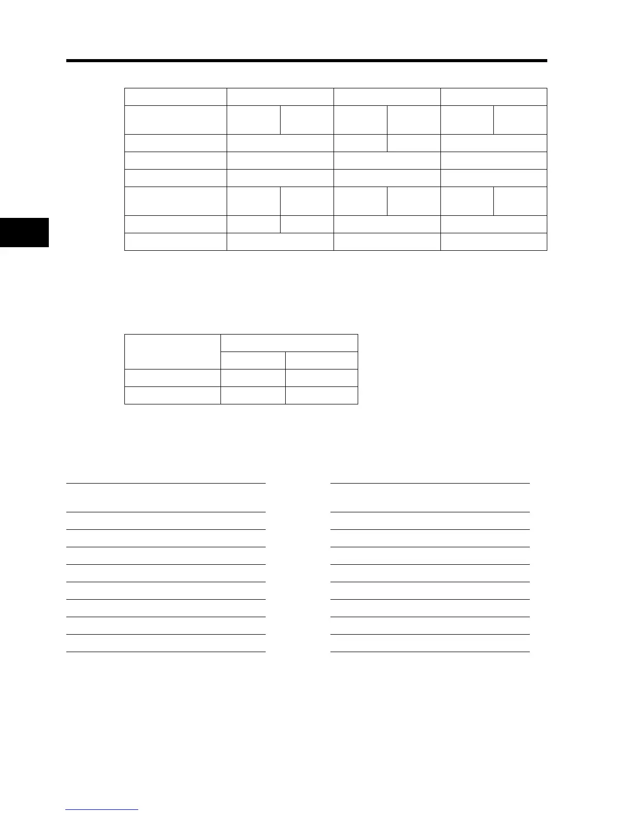
Read the data received in the response, as follows:
Refer to "<Exception Response>" (4-75) if the holding register content reading command has not
been performed normally.
<Writing Into the Coil [05h]>
Writes into one coil.
The coil status change is shown in the following table.
(Example)
•Issues the RUN command to the Inverter with the slave address "8". For running, "03" must be set
to "A002".
•The coil number of the RUN command is "1".
*1. There is no response for broadcasting.
*2. Note that the coil start address is "0", which is smaller by 1 than the coil number "1". The coil
addresses for coil numbers from "1 to 31" are "0 to 30".
Refer to "<Exception Response>" (4-75) if writing into the coil cannot be performed normally.
Response buffer 4-5 6-7 8-9
Holding register start
number
12+0
(MSB)
12+0
(LSB)
12+1
(MSB)
12+1
(LSB)
12+2
(MSB)
12+2
(LSB)
Response data 0003h 00h 00h 0063h
Trip data Trip factor (03) Not used Frequency (9.9 Hz)
Response buffer 10-11 12-13 14-15
Holding register start
number
12+3
(MSB)
12+3
(LSB)
12+4
(MSB)
12+4
(LSB)
12+5
(MSB)
12+5
(LSB)
Response data 00h 00h 001Eh 001Ch
Trip data Not used Output current (3.0 A) DC bus V DC (284V)
Data
Coil status
OFF → ON ON → OFF
Change data (MSB) FFh 00h
Change data (LSB) 00h 00h
Query Response
No. Field name
Example
(Hex)
No. Field name
Example
(Hex)
1 Slave address
*1
08 1 Slave address 08
2 Function code 05 2 Function code 05
3 Coil address
*2
(MSB) 00 3 Coil address
*2
(MSB) 00
4 Coil address
*2
(LSB) 00 4 Coil address
*2
(LSB) 00
5 Change data (MSB) FF 5 Change data (MSB) FF
6 Change data (LSB) 00 6 Change data (LSB) 00
7 CRC-16 (MSB) 8C 7 CRC-16 (MSB) 8C
8 CRC-16 (LSB) A3 8 CRC-16 (LSB) A3