2-21
2-2 Wiring
2
Design
Specifications of the Control Circuit Terminals
Terminal
symbol
Terminal name and function Default setting Specifications
Input signal
PCS
External power supply terminal for input
signal (input).......................At sink logic
Internal power supply output terminal for
input signal (output)......At source logic
⎯
24 V DC ±10%
30 mA max.
24 V DC ±10%
100 mA max.
1
Multi-function input terminals 1 to 5
Select 5 functions among the 31
functions and allocate them to from
terminals 1 to 5.
The terminal allocation is changed
automatically when the emergency
shutoff function is used. Refer to
"Emergency Shutoff Input Function"
(page 4-46).
Forward/Stop
Contact input
Close: ON (Start)
Open: OFF (Stop)
Minimum ON time:
12 ms min.
2 Reverse/Stop
3 Fault reset
4
Emergency stop
fault
5
Multi-step speed
reference 1
L Input signal common ⎯
Monitor
signal
AM
Analog frequency monitor/
Analog output current monitor
Analog
frequency
monitor
Frequency
reference
input
H Frequency reference power supply ⎯
10 V DC
10 mA max.
O Voltage frequency reference signal ⎯
0 to 10 V DC
Input impedance 10 kΩ
When installing variable
resistors at FS, FV, and FC
(1 to 2 kΩ)
OI Current frequency reference signal ⎯
4 to 20 mA DC
Input impedance 250 Ω
L Frequency reference common ⎯
Output signal
11
Multi-function output terminal
Select the status of the Inverter and
allocate it to terminal P1.
Frequency
arrival signal at
a constant
speed
27 V DC
50 mA max.
CM2 Output signal common ⎯
Relay output
signal
AL2
Under normal operation : AL2-AL0 Closed
Under abnormal operation or power
shutdown : AL1-
AL0 Open
(Default)
Contact ratings
250 V AC 2.0 A (resistance load) 100 V AC min.
0.2 A (inductive load) 10 mA
30 V DC 3.0 A (resistance load) 5 V DC
0.6 A (inductive load) 100 mA
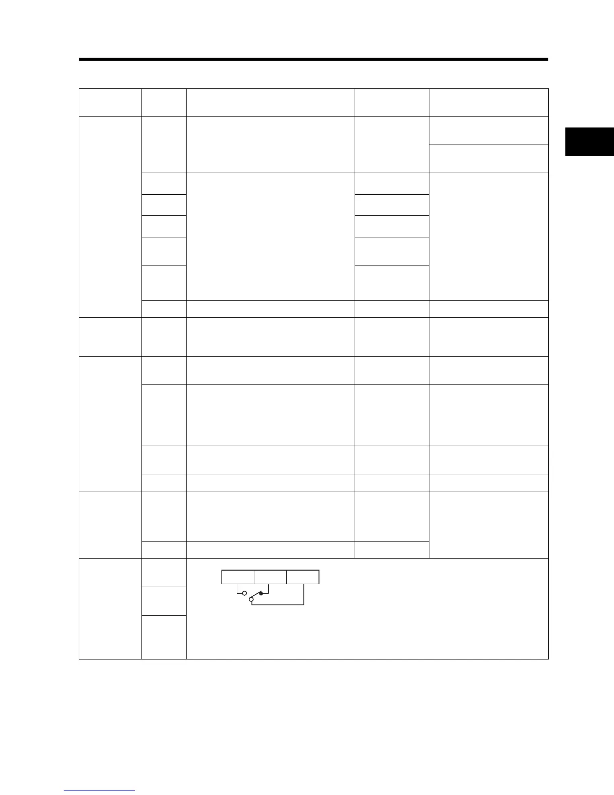
AL1
AL0
AL1 AL2 AL0