3-18
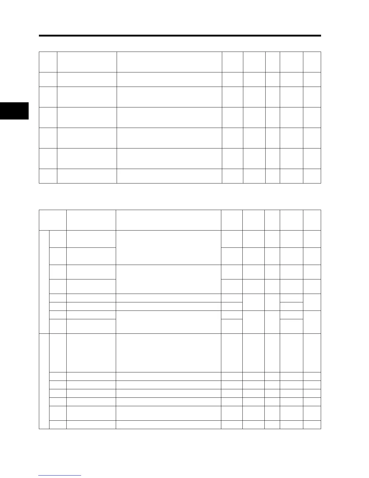
3-6 Parameter List
3
Operation
Basic Function Mode (F)
* 2nd control is displayed when SET(08) is allocated to one of the digital inputs.
Extended function mode
Parm
No.
Name
Monitor or data range
(Digital Operator)
Default
setting
Change
during
Run
Unit
Modbus
Address
(Hex)
Page
F001
Output frequency setting/
monitor
Starting frequency to 1st or 2nd max. frequency ⎯ Yes Hz - 4-6
F002 Acceleration time 1
0.01 to 99.99
100.0 to 999.9
1000. to 3000.
10.0 Yes s
1014 M
1015 L
4-6
F202
*2nd acceleration
time 1
0.01 to 99.99
100.0 to 999.9
1000. to 3000.
10.0 Yes s
1501 M
1502 L
4-6
F003 Deceleration time 1
0.01 to 99.99
100.0 to 999.9
1000. to 3000.
10.0 Yes s
1016 M
1017 L
4-6
F203
*2nd deceleration
time 1
0.01 to 99.99
100.0 to 999.9
1000. to 3000.
10.0 Yes s
1503 M
1504 L
4-6
F004
Operator rotation direction
selection
00: Forward
01: Reverse
00 No ⎯ 1018 4-7
Parameter
No.
Function name
Monitor or data range
(Digital Operator)
Default
setting
Change
during
Run
Unit
Modbus
Address
(Hex)
Page
Basic setting
A001
Frequency reference
selection
00: Digital Operator (FREQ adjuster)
01: Terminal
02: Digital Operator (F001)
03: ModBus communication
10: Frequency operation result
00 No ⎯ 1019 4-8
A201
*2nd frequency
reference selection
00 No ⎯ -4-8
A002
RUN command
selection
01: Terminal
02: Digital Operator
03: ModBus communication
02 No ⎯ 101A 4-8
A202
*2nd RUN command
selection
02 No ⎯ -4-8
A003 Base frequency 30. to Max. frequency [A004] 50
No Hz
101B
4-9
A203 *2nd base frequency 30. to Max. frequency [A204] 50 150C
A004 Maximum frequency
30. to 400.
50
No Hz
101C
4-10
A204
*2nd maximum
frequency
50 150D
Analog input
A005 O/OI selection
02: Switches between O/FREQ adjuster via
terminal AT
03: Switches between FI/FREQ adjuster via
terminal AT
04: O input only
05: OI input only
02 No ⎯ 101D 4-10
A011 O start frequency 0.0 to Max. frequency 0.0 No Hz 1020 4-11
A012 O end frequency 0.0 to Max. frequency 0.0 No Hz 1022 4-11
A013 O start ratio 0. to 100. 0. No % 1023 4-11
A014 O end ratio 0. to 100. 100. No % 1024 4-11
A015 O start selection
00: External start frequency (A011 set value)
01: 0 Hz
01 No ⎯ 1025 4-11
A016 O, OI sampling 1. to 17. 8. No ⎯ 1026 4-12