2-9
2-2 Wiring
2
Design
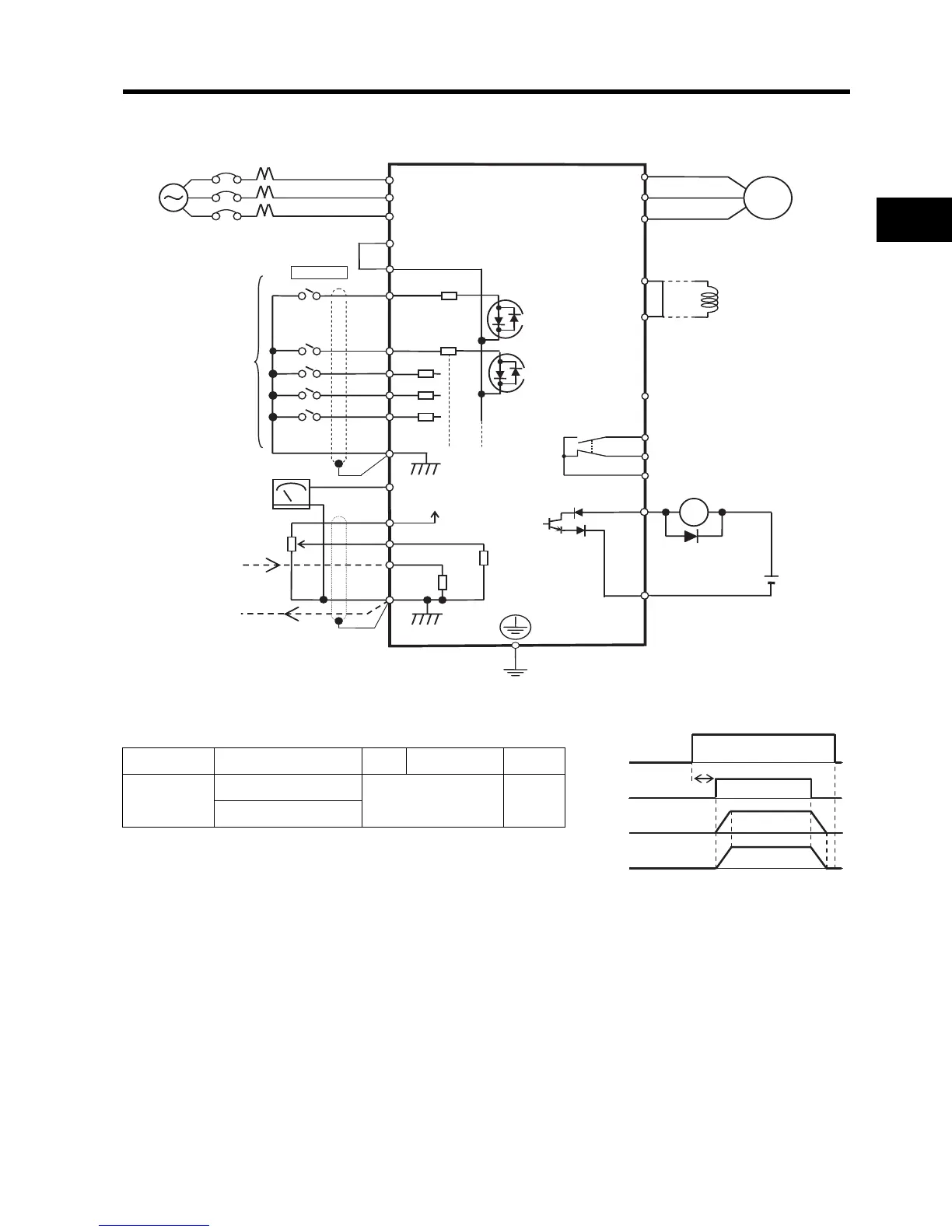
Standard Connection Diagram
Different terminals have different commons.
*1.) Use terminals L1 and N for single phase model JX-AB
*2.) If the main circuit is turned on at the same time as a RUN command is input, the motor begins to rotate at
least 2.0 seconds later.
Secure a duty cycle of 5 minutes or more between switching the power ON/OFF. Otherwise, the life of the
Inverter is shortened.
Do not turn off the main circuit during operation.
Terminals 1, 2, 3, 4, 5 AM H, O, OI 11
Commons
Sink logic - L
LCM2
Source logic - PCS
Inverter
R/L1 (L1)
S/L2 (L2)
T/L3 (N/L3)
PCS
P24 24V DC
U/T1
V/T2
W/T3
Motor
Note:
To connect the DC reactor,
remove the short-circuit bar.
For Sink logic
5
4
4.7 kΩ
3
2
1
L
PD/+1
DC reactor
P/+
N/-
11
24 V DC
CM2
10 kΩ
250 Ω
10 V DC
L
OI
O
H
AM
Frequency meter
Frequency
setting unit
1 to 2 kΩ
4 to 20 mA DC
Power supply input
Relay output
Common
AL1
AL2
AL0
RY
3-phase 200 V AC
1-phase 200 V AC *1
3-phase 400 V AC
Multi-function input 1
Multi-function input 2
Multi-function input 3
Multi-function input 4
Multi-function input 5
Multi-function output
Multi-function output common
Analog monitor output
Main circuit power supply
RUN command
Output frequency
Motor rotation speed
*2
2.0 s min.