4-22
4-2 Function Mode
4
Functions
PID Function
This function enables process control of such elements as flow rate, air volume, and pressure.
•To use this function, set A071 to 01.
•To switch between enable/disable via the terminal block (external signal), allocate 23 (PID enable/
disable) to the desired multi-function input. Select OFF for enable and ON for disable.
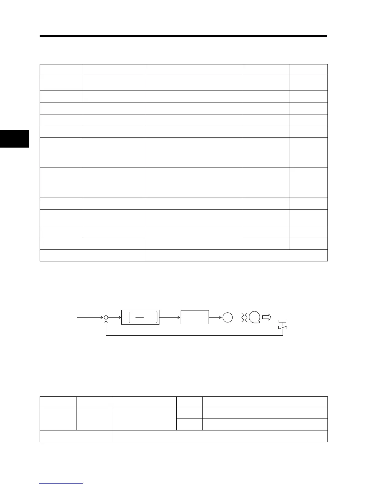
Basic Structure of PID Control (Example)
PID Enable/Disable
The PID enable/disable function disables the PID function temporarily through terminal input. This
overrides the A071 setting to control the motor frequency.
Parameter No. Function name Data Default setting Unit
A071 PID selection
00: Disabled
01: Enabled
00 ⎯
A072 PID P gain 0.2 to 5.0 1.0 ⎯
A073 PID I gain 0.0 to 150.0 1.0 s
A074 PID D gain 0.00 to 100.0 0.0 s
A075 PID scale 0.01 to 99.99 1.00 Time
A076 PID feedback selection
00: OI
01: O
02: RS485 communication
03: Operation function output
00 ⎯
A077 Reverse PID function
00: Deviation = Target value -
Feedback value
01: Deviation = Feedback value -
Target value
00 ⎯
A078 PID output limit function 0.00 to 100.0 0.0 %
C044
PID deviation excessive
level
0. to 100. 3.0 %
C052 PID FB upper limit
0.0 to 100.0
100 %
C053 PID FB lower limit 0.0 %
Related parameters d004, A001, A005, C001 to C005, C021, C026
fs
M
=
+
-
Deviation ε
ε: Deviation
sT
sT
K
d
i
p
1
1
Target value
0 to 10 V
4 to 20 mA
+
·
·
+
Control
value
Feedback 0 to 10 V
4 to 20 mA
Normal control
of the Inverter
Transducer
Sensor
Kp: Proportional gain Ti: Integral time Td: Derivative time s: Operator
Data Symbol Function name Status Description
23 PID PID enabled/disabled
ON Disables the PID function.
OFF Does not affect the PID function.
Related parameters
C001 to C005