2-19
2-2 Wiring
2
Design
Wiring the Main Circuit Terminals (Output Side)
Connect the Terminal Block to the Load
•Connect motor output terminals U/T1, V/T2, and W/T3 to motor lead wires U, V, and W.
•Check that the motor rotates forward with the forward command. Switch over any two of the output
terminals (U/T1, V/T2, W/T3) and reconnect if the motor rotates in reverse to the forward
command.
Never Connect a Power Supply to the Output Terminals
•If voltage is applied to the output terminals, the internal circuit of the Inverter will be damaged.
Never connect a power supply to output terminals U/T1, V/T2, or W/T3.
Never Short-circuit or Ground the Output Terminals
•Never touch the output terminals by hand.
•If the output wires come into contact with metal materials, an electric shock or ground fault will
occur. This is extremely hazardous. Be careful not to short-circuit the output wires.
Do Not Use a Phase Advance Capacitor or Noise Filter
•Doing so may result in damage to the Inverter or cause the parts to burn. Never connect a phase
advance capacitor or LC/RC noise filter to the output circuit.
Do Not Use an Electromagnetic Switch
•If a load is connected to the Inverter during running, an inrush current will actuate the overcurrent
protective circuit in the Inverter. Do not connect an electromagnetic switch or magnetic contactor
(MC) to the output circuit.
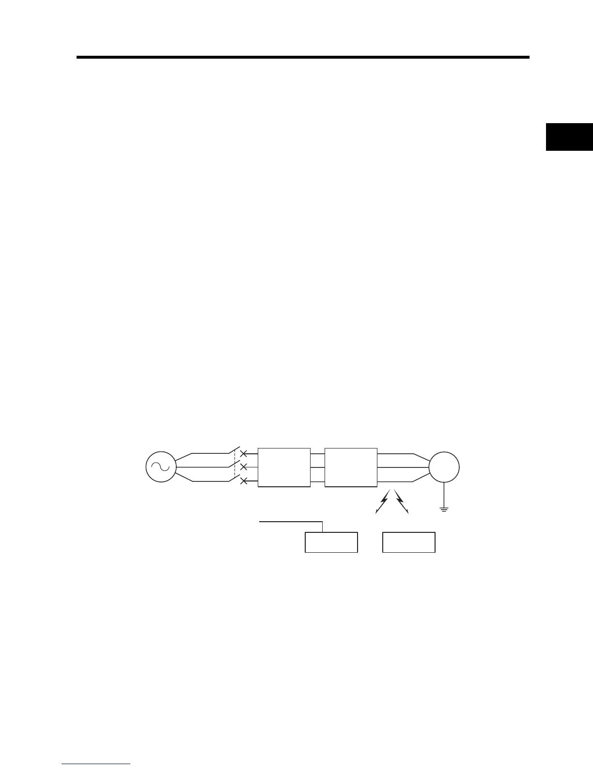
Install a Noise Filter on the Output Side
Connect a noise filter to the output side of the Inverter to reduce induction and radio noise.
Countermeasures Against Induction Noise
To reduce induction noise from the output side, the following method is also effective.
M
Molded-case circuit breaker
(MCCB)
Power
supply
Inverter
JX
Noise filter
3G3AX-NFO
Radio noise
AM radioController
Induction noise
Signal line
Induction noise: Electromagnetic induction can generate noise on the signal line, causing the
controller to malfunction.
Radio noise: Electromagnetic waves from the Inverter and I/O cables can cause the radio receiver
to generate noise.